
By accurately determining the load power, engineers and designers can assess how effectively electrical energy is being converted into useful work in electronic circuits.
The power used by an electrical load in a circuit is called load power, sometimes called real power or active power. The basic formula for power is the function of voltage and current. Various power equations are used to calculate load power, some of which are derived from Ohm’s law. We will discuss resistive, inductive, and capacitive loads.
In this article, we’ll delve into the concepts and methods behind load power calculation.
Introduction to load power
The power consumed by the device or load in the circuit is known as load power. It shows how quickly electrical energy is transformed within the load into productive work.
Typically, load power is expressed in watts (W) or kilowatts (kW).
In the circuit, power is transmitted to the load, which consumes that power and performs a specific task.
The load power provides the energy/power needed to perform tasks like turning on an electric lightbulb, moving an electric motor, or powering electronics.
Knowing load power is essential for multiple uses, such as creating effective electronic systems, controlling energy usage, projecting electricity expenses, and guaranteeing the secure and reliable functioning of various circuits.
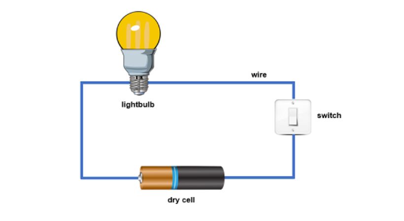
In the above circuit, a battery provides voltage, and current starts flowing that gives the power to the bulb in the circuit to light up so here the provided power is converted into useful light energy.
Remember that if you want to get started with electronics, understanding the load power calculation concept is very crucial for circuit design as you have to know how much power a component can consume.
There are various types of load and for each load, different power equations are used to calculate its power. Let’s discuss each.
1. Resistive load
A resistive load is one in which the current and voltage are in phase, meaning the current drawn by the load and the voltage across it increase and decrease at the same time.
These loads just convert electrical energy into heat and do not store it.
They are used in applications where constant power dissipation is required, such as in heating elements, testing of power supplies, and controlling current in circuits.
The formula for resistive load power calculation is the function of voltage and current. So the power ‘P’ is given by
P=VI
Where ‘I’ represents current and ‘V’ represents voltage in the circuit. Some other formulas are derived by using Ohm’s Law. When we put the formula of current and voltage obtained by Ohm’s law the power becomes
P=I^2R
And
P=V^2/R
All these equations are used to calculate the power of resistive load in a DC circuit depending upon the known quantity.
In AC circuits, the real power is:
P=V_rms*I_rms*cos(ɸ)
For purely resistive loads, cos(ɸ)= 1 because voltage and current are in phase, so:
P=V_rms*I_rms
Example resistive load:
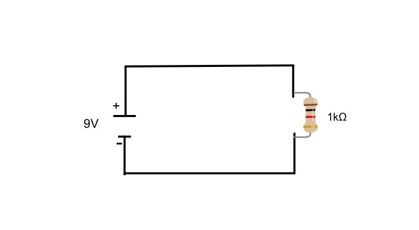
You can find the circuits in different combinations with load. Solving and simplifying these circuits is tricky. Let’s discuss how load power will be calculated.
In the first example, we have three resistors of value 10Ω, 20Ω, and 30Ω which are connected to a 12V power supply. What will be the power delivered to resistors? Let’s find out.
Given:
V_s=12V, R_1=10Ω, R_2=20Ω, R_3=30Ω
Required:
Total power delivered by voltage source P_t
Power delivered to each resistor, P_1, P_2, P_3
Solution:
As we know power is equal to
P =VI
We know voltage but the current is unknown in the circuit. Let’s find the current first, for current we have to find the resistance equivalent.
R_T=R1+R2+R3
R_T=10+20+30
R_T=60Ω
Now
I=V_s/R_T
I=12V/60Ω
I=0.2A
The resistors are in series so the same amount of current is passing through them. So total power is equal to
P_t=V_s*I
P_t=(12)*(0.2)
Pt=2.4W
To find the power of each resistor we have to find the voltage drop in each resistor.
V_1=I*R_1
V1=(0.2)*(10)
V_1=2V
Now
P_1=I*V_1
P_1=(0.2)*(2)
P_1=0.4W
The same steps will be followed to find the power of the other two resistors. The power of the other two resistors is P2=0.8W and P3=1.2W.
Calculate the power of the other two resistors, and write it down in the comment section.
2. Capacitive load
A capacitive load stores energy in the form of an electric field when voltage is applied across its terminals. The current leads the voltage by 90° in capacitive circuits, which is opposite to the behavior of inductive loads.
In capacitive load, the energy is stored and can be released later. In a purely capacitive circuit, the phase angle between current and voltage is +90°.
In capacitive loads, we have three types of power so three equations are used to calculate power.
Real power: It is the type of power that is the actual power consumed by the load to convert it into useful work. However, in a purely capacitive load, the energy is stored and released, and no real power is consumed in the ideal case.
Real power in a purely capacitive load is ideally zero because no net energy is consumed.
As we know,
P=V_rms*I_rms*cos(ɸ)
For a purely capacitive load, ɸ=90° (phase difference), and cos(90°) = 0 so:
P=0 W
Reactive power: It is the power due to the energy oscillation back and forth between the source and the components. This reactive power is due to the storage and release of energy in the electric field of the capacitor in the capacitive loads.
Unlike real power, reactive power does not perform useful work but affects the overall power flow in the system.
The reactive power is given by:
Q=V_rms*I_rms*sin(ɸ)
For purely capacitive load, ɸ = 90° and sin(90°)=1
Q=V_rms*I_rms
However, since capacitive loads return power to the source, the reactive power is considered negative:
Q= -V_rms*I_rms
Apparent power: It is the total power supplied to the load from the source, which includes both real and reactive power.
It is calculated as.
S= sqrt (P^2+Q^2)
As the real power (P) for capacitive load is zero the equation becomes
S=|Q|
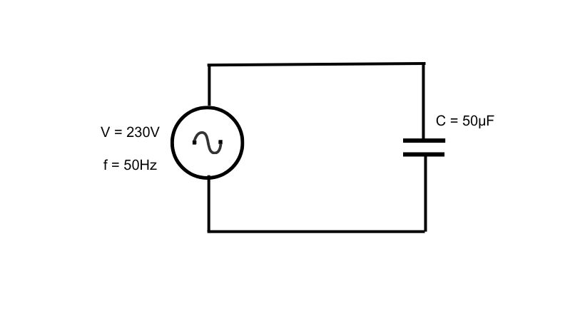
Example
We have a pure capacitive load with phase ɸ = -90°, V_rms=230V, I_rms=5A. Let’s calculate its power.
The real power is zero for a pure capacitive load.
The reactive power is given by:
Q=V_rms*I_rms*sin(ɸ)
Q=230* 5 *sin(-90°)
Q= -1150W
And the apparent power is equal to reactive power so,
S=|Q|
S=|-1150|
S=1150W
This is how power is calculated for a purely capacitive load.
3. Inductive load
An inductive load stores energy in a magnetic field, causing the current to lag the voltage by 90°.
Inductive loads consume reactive power for the creation of the magnetic field, and some real power due to resistance in the winding or core losses (for motors or transformers).
The real power of the inductive load is the same as the resistive load for the AC circuit.
P=V_rms*I_rms*cos(ɸ)
Where:
Cos (ɸ) Is the power factor, typically less than 1 for inductive loads because of the phase difference.
The reactive power for inductive loads is:
Q=V_rms*I_rms*sin(ɸ)
ɸ Is the phase angle, usually between 0° and 90° for inductive loads (lagging current).
Apparent power is the total power supplied by the source and it is given by
S= sqrt(P^2+Q^2)
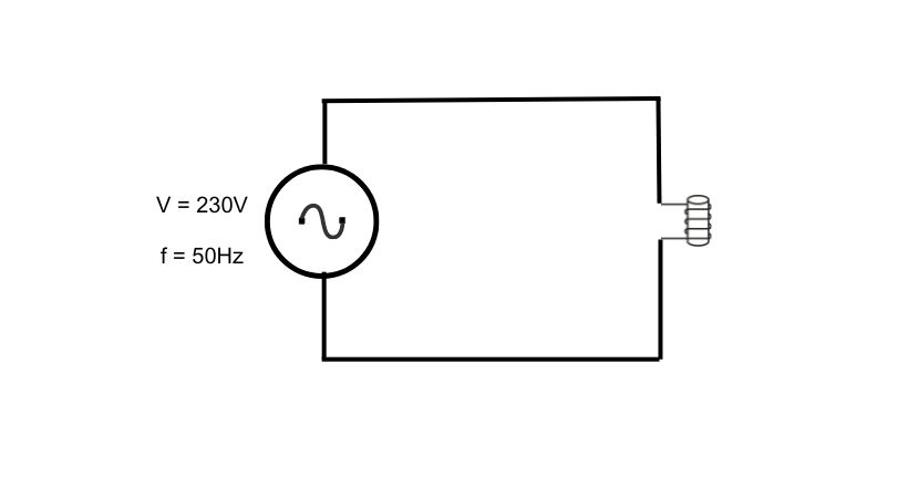
Example:
For an inductive load with:
- Vrms=230
- Irms=10 A
- Phase angle ϕ=30° and cos(30°) = 0.866
Real power:
P=V_rms*I_rms*cos(ɸ)
P=230*10*cos(30)
P=1991.8W
Reactive power:
Q=V_rmsI_rms*sin(ɸ)
Q=230*10*sin(30)
Q=1150 W
Apparent power:
S= sqrt(P^2+Q^2)
S=2300W
These are some examples of load power calculations for different types of electric loads.
Conclusion
Load power calculation is a fundamental concept in electrical engineering and is essential for understanding and managing electrical systems.
By considering voltage, current, and power factor, you can determine how efficiently electrical energy is being converted into useful work. Power is the rate at which energy is transferred into the electrical circuit.
The actual power used by an electrical load in an electrical circuit is called load power. Power is the function of voltage and current so the power formula is P=VI for resistive load.
In capacitive and inductive loads the current and voltage lag so it has a power factor in the formula.
By following step by step process you can simplify complicated to complicated circuits and can find their power dissipation.
This was all about load power calculation. I hope this blog post has helped clarify the concept.
Thank you and stay blessed…
Other useful posts: