In every other electronic device, transistors are found, making it crucial to understand their ratings.
Transistor ratings provide valuable information about their performance limits and help engineers select the right transistor for a specific application. In the transistor datasheet, we have information related to its maximum ratings, thermal, and electrical characteristics. The maximum rating section has the maximum values of various parameters that the transistor can safely handle, and the electrical characteristics section of a transistor datasheet provides detailed information about how the transistor behaves under specific operating conditions.
In this article, we will provide a comprehensive guide to understanding transistor ratings.
Transistor ratings
The transistor is a three-terminal semiconductor device used as an amplifier or an electronic switch.

To use the transistor properly and to make sure it doesn’t damage due to overheating or high applied voltage and current understanding its ratings is essential.
Transistor ratings are the specifications and limits that define the operating conditions and performance capabilities of the transistors.
These ratings provide valuable information about the maximum allowable values of various parameters, such as current, voltage, power, and frequency, that the transistor can handle without any damage.
Understanding transistor ratings is crucial for selecting the right transistor for a specific application and ensuring its proper and reliable operation.
The datasheet of the transistor provides information about the different parameters of the transistor.
Let’s discuss these ratings in detail.
Maximum ratings
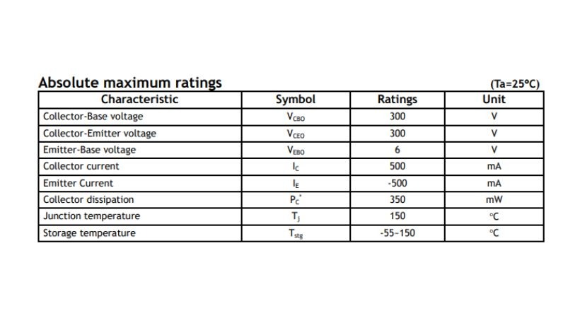
The maximum ratings define the various parameters that a transistor can handle without causing any damage to itself and other components.
The datasheet of the transistor provides all information related to transistor ratings. Below are the transistor maximum ratings from the datasheet.

These ratings indicate the maximum values that should not be exceeded during normal operation to ensure the reliability and longevity of the transistor.
The common maximum ratings include:
1. Collector-emitter voltage (VCEO, VCE)
The maximum collector-emitter voltage rating indicates the highest voltage that can be applied across the collector and emitter terminals of the transistor without causing breakdown or damage. It is specified in volts (V).
Operating the transistor above this voltage rating can result in current leakage, breakdown, or even destruction of the device.
2. Collector-base voltage (VCBO, VCBmax)
Collector-base voltage (VCB) is a key parameter in a transistor datasheet that specifies the maximum voltage that can be applied across the collector and base terminals of the transistor without causing breakdown or damage.
It represents the voltage that can be safely applied in the reverse-biased direction between the collector and base.
The collector-base voltage rating is typically denoted as VCB(max) or VCBO (maximum collector-base voltage when the emitter is open), and it is specified in volts (V).
Try to operate the transistor within the mentioned limits because Exceeding this voltage rating can lead to current leakage, breakdown of the transistor’s internal junctions, and potential damage to the device.
3. Emitter-base voltage (VEBO, VEBmax)
The maximum voltage that can be applied between the emitter and base terminals of a transistor without causing breakdown or damage is expressed by emitter-base voltage.
The emitter-base junction is forward-biased and the emitter is heavily doped so when voltage is applied to the emitter to the base, it allows the current to flow from the emitter to the base region.
The maximum emitter-base voltage rating is provided to ensure that the transistor operates within safe limits and to prevent breakdown. In breakdown, excess current flow causes damage to the transistor.
4. Collector current (IC,ICmax )
The maximum collector current rating determines the highest current that the transistor’s collector terminal can handle without exceeding its operating limits.
It is usually specified in units of amperes (A). Exceeding this rating can lead to overheating, excessive voltage drops, and potentially damaging the transistor.
It is recommended that operate the transistor within the mentioned limits for safe and reliable operation.
5. Base current (IB, IBmax)
The maximum base current rating specifies the maximum current that can be applied to the transistor’s base terminal. It is expressed in amperes (A).
As the base current controls the collector current, applying a higher base current than the specified maximum rating can result in excessive collector current and potential damage to the transistor.
Look for the base current in the datasheet while selecting any transistor. Make sure that the transistor can handle the current flowing in the circuit.
6. Maximum power dissipation (PD)
The maximum power dissipation rating defines the maximum amount of power that the transistor can safely dissipate as heat without exceeding its temperature limits.
It defines two types of power dissipation at various temperatures: TA, TC.
The TA represents the ambient temperature, which is the temperature of the surrounding environment in which the transistor operates. This refers to the maximum power that the transistor can dissipate at the specified ambient temperature (TA).
The TC represents the case temperature, which is the temperature at the surface of the transistor’s package or case. This refers to the actual power dissipation of the transistor at the case temperature (Tc).
It is typically given in watts (W) or milliwatts per celsius (mW/C. Exceeding this rating can cause the transistor to overheat, leading to degradation or failure.
7. Junction temperature (TJ)
The junction temperature rating specifies the highest temperature that the transistor’s junction can reach under normal operating conditions without causing damage or degradation.
It is typically given in degrees Celsius (°C). Operating the transistor above this temperature can lead to reduced performance, shortened lifespan, or permanent failure.
Make sure you understand and operate the transistor within the junction temperature limits.
8. Storage temperature (TStg)
In transistor ratings, the storage temperature is also defined along with the junction temperature.
The storage temperature rating in transistor ratings refers to the range of temperatures within which the transistor can be safely stored or stored without degradation or damage to its performance.
The storage temperature rating is typically provided as a range of temperatures, such as -50°C to +150°C, and it is specified in degrees Celsius (°C). The -50°C is the lower limit and +150°C is the upper limit.
Thermal characteristics
The thermal characteristics of a transistor refer to the properties and behaviors related to its thermal management and heat dissipation.

Understanding the thermal characteristics is crucial for designing appropriate cooling solutions and ensuring the reliable operation of the transistor in practical applications.
Some important thermal characteristics of transistors include:
1. Thermal resistance (θ)
Thermal resistance is a key parameter that quantifies the ability of a transistor to transfer heat from its active region (junction) to the surrounding environment.
It is typically expressed in degrees Celsius per watt (°C/W). There are different types of thermal resistance specified in transistor datasheets:
a. Junction-to-case thermal resistance (θJC):
This parameter represents the thermal resistance between the transistor’s junction and its case or package.
It indicates how efficiently heat can be transferred from the transistor’s active region to the transistor’s external surface or heat sink.
b. Junction-to-ambient thermal resistance (θJA):
This parameter represents the thermal resistance between the transistor’s junction and the ambient environment. The ambient environment means the surroundings environment in which the transistor is operating.
It takes into account the overall heat dissipation from the transistor, considering the thermal resistance of the case, circuit board, and any cooling mechanisms in use.
Understanding these thermal characteristics is very essential for designing effective cooling solutions and selecting appropriate heat sinks.
Electrical characteristics
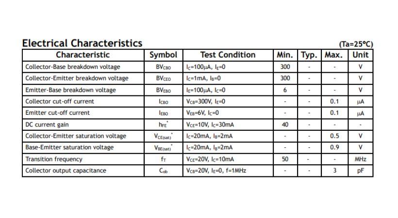
The electrical characteristics section of a transistor datasheet provides detailed information about how the transistor behaves under specific operating conditions.

It includes various parameters and graphs that describe the transistor’s electrical behavior, performance, and relationships between different terminal voltages and currents.
In this section, the manufacturer provides different testing conditions and calculates different parameters of the transistor.
Let’s discuss the different parameters included in this section.
1. DC gain (hFE, β)
The DC gain represents the ratio of the output current (collector current, IC) to the input current (base current, IB) when the transistor is in the active region. It is a measure of the transistor’s amplification capability.
In the datasheet, different hFE or β values will be given on different applied voltages. The maximum and minimum range hFE is also given.
For example, if a transistor has an hFE of 100, it means that a small base current of, let’s say, 10 microamps can result in a collector current of 1 milliamp. The hFE value can vary depending on the collector’s current and other operating conditions.
Understand your applications and select the transistor with appropriate hFE.
2. Collector-emitter saturation voltage (VCE(sat))
This characteristic indicates the voltage drop between the collector and emitter terminals of the transistor when it is fully turned on and saturated.
In saturation mode, the transistor acts like a closed switch, allowing a relatively high collector current to flow with a low voltage drop.
The VCE(sat) rating is important when using the transistor as a switch to ensure that the voltage drop across the transistor remains within acceptable limits.
3. Base-emitter voltage (VBE)
The voltage drop between the emitter and base is given by the base-emitter junction when it is in the active region. This is the minimum voltage required for the transistor to be forward-biased.
For current to flow in the transistor this voltage is required. The VBE value depends on the transistor’s type, material, and temperature.
4. Collector-cutoff current (ICBO)
ICBO an electrical characteristic of a transistor represents a small leakage current flowing between the collector and the base terminals when the transistor is in the cutoff or off state.
It is the current that flows from the collector terminal to the base terminal when no current is applied to the base terminal (IB = 0).
It is typically very small, ranging from a few nanoamperes (nA) to a few microamperes (µA), and can be affected by factors such as temperature and the specific characteristics of the transistor.
5. Emitter-cutoff current (IEBO )
The emitter-cutoff current (IEBO ) is an electrical characteristic of a transistor that represents the small leakage current flowing between the emitter and base terminals when the transistor is in the cutoff or off state.
In the cutoff state, the transistor is biased in a way that prevents significant current flow between the emitter and base.
However, due to various factors such as temperature and manufacturing imperfections, a small amount of leakage current may still exist.
The IEBO is typically very small, ranging from a few nanoamperes (nA) to a few microamperes (µA).
Understand and learn about each rating of the transistor before selecting it because any negligence can cost you more.
Conclusion
The transistor ratings define the specific parameters and limitations for the proper operation of the transistor.
To avoid the damage and burnout of the transistor understanding of transistor rating is essential.
When you look at the transistor’s datasheet, the three major headings, such as maximum ratings, thermal, and electrical characteristics, will always be present.
The maximum ratings define the maximum values that a transistor can handle without damaging itself. The thermal characteristics of the transistor define its heat dissipation and thermal properties.
Conversely, electrical characteristics define the operating behaviors of transistors under specific conditions. This section also includes some graphs for better understanding.
That’s it, this was all about the transistor ratings. I hope you’ll learn a lot from it.
Thank you and stay blessed…
Other useful posts:
