The electronic components in the circuit are connected in two different ways: Series and parallel. The resistor is the component that controls the flow of current.
With the help of multimeter series parallel resistance verification can be done. Resistors connected end-to-end forming a single path, then when one probe of multimeter to one end of the resistor and the other to the other end of the last resistor, the multimeter will show the resistance greater than the greatest resistor. The same process is for parallel but in parallel the multimeter will show the resistance value smaller than the smallest resistor in the circuit.
In this article, we’ll discuss series parallel resistance verification using a multimeter.
Series parallel resistance verification using a multimeter
Before diving into series and parallel resistance verification, let’s briefly discuss some basics of a multimeter.
A multimeter is a versatile electronic instrument designed to measure various electrical properties such as voltage, current, and resistance.
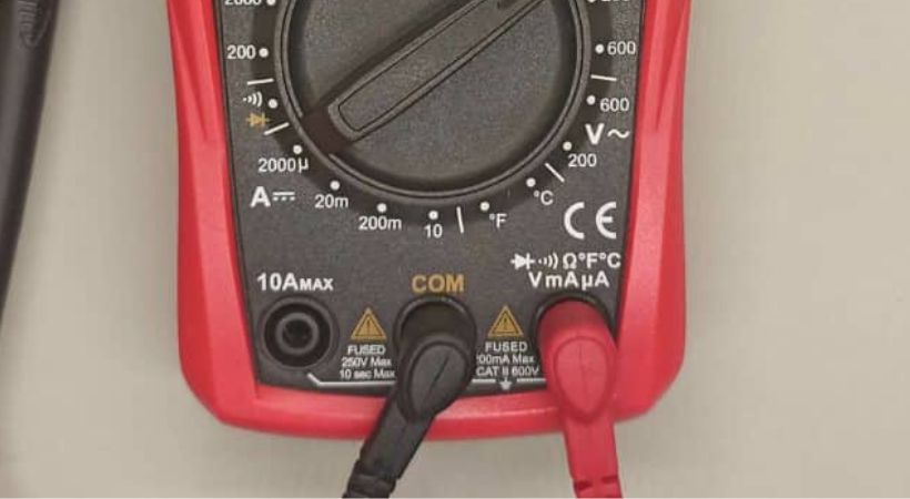
It typically consists of a display (either analog or digital), a selection dial or buttons for choosing measurement functions, and input jacks for connecting test leads or probes.
For any electrical parameter, the setting of the multimeter is very crucial. So let’s talk about how can you set your multimeter for various measurements.
Setting up the multimeter
Setting up the multimeter means selecting the appropriate measurement function and range for the parameter you want to measure.
The various options are available on the multimeter so you have to select one of them according to your need.
Here are some general steps to set up a multimeter for various measurements:
- Turn on the multimeter, if your multimeter has an On/off option.
- The next step is to connect the multimeter probes, it has two probes: black and red.
- Connect the black probe to the COM (common) jack, and the red test probe to the jack labeled for the measurement you’re making.

- Now select the function or parameter you want to measure, in our case the function is resistance mode.
- Rotate the selection towards the Ω sign.
- Here is the main point, if you’re using a manual range multimeter you also have to select the measurement range and if you are using an auto range multimeter this step is not required.
- You can also test your multimeter for open and short circuits.
- Leave the probes of the multimeter untouched, if the multimeter shows “OL” or 1, it means the multimeter is good.
- When touching the probes it displays zero resistance, which also means the multimeter is accurate for further measurements.
By following these steps and selecting the correct measurement function and range, you can effectively set up a multimeter for various measurements in electronic circuits.
Now the multimeter is set to verify the series and parallel connection of the resistors.
Series resistors verification
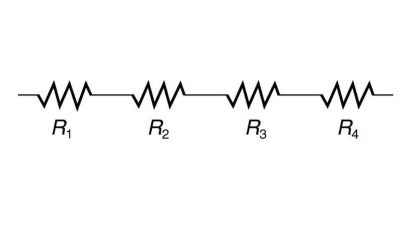
In a series combination of resistors, individual resistors are connected end-to-end, forming a single pathway for current to flow through.

This means that the same current flows through each resistor in the series.
The total resistance in a series circuit is the sum of the resistances of all the resistors connected in series.
For example, if you have three resistors connected in series with resistances of 10Ω,20Ω, and 30Ω, respectively, the total resistance of the series combination would be 10Ω+20Ω+30Ω=60Ω.
As you can in the above example the resultant resistance of the series resistors is greater than the greatest resistor. This is the key point for verification of the series combination of the resistors.
Series resistance verification:
Verifying series resistance using a multimeter is a straightforward process.
Follow these steps:
- Disconnect the power to the circuit before performing measurements.
- Select the resistance mode of the multimeter.
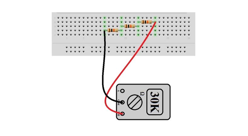
- Now connect the multimeter across each resistor and the result will be displayed on the screen, note the resistance of each resistor.
- If you know the resistance of each resistor, you can skip the above step.
- Now measure the resistance across the entire series chain by touching one probe to one end and the other probe to the other end, which means connecting the one probe to one end of the first resistor and the other probe to the end of the last resistor.

- The resultant resistance on the screen will be greater than the larger resistor connected in the series.
By following these steps, you can confidently verify the series combination of resistors using a multimeter. This knowledge is invaluable for circuit analysis, troubleshooting, and design in various electronic applications.
Parallel resistors verification
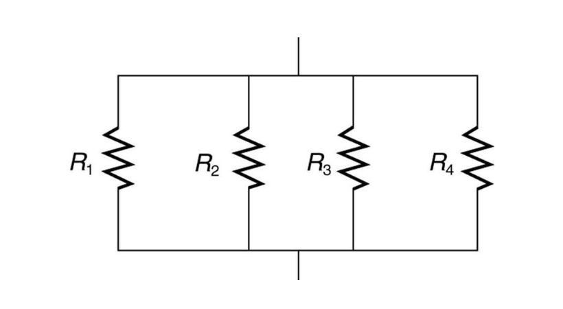
The parallel combination of the resistors is the combination in which there are multiple paths for the current to flow.

Each resistor in parallel has the same voltage across it but a different current.
The key point to remember the equivalent resistance (R_total) of a parallel combination of resistors is always less than the resistance of the smallest resistor in the parallel group.
This is because adding more paths for current to flow decreases the overall resistance of the circuit.
Parallel resistance verification:
Follow these simple steps to verify the parallel combination of the resistors.
- Disconnect the power to the circuit before taking any measurements.
- Set the multimeter to measure resistance (Ω).
- In parallel combination, make sure the resistors are connected to the same row of breadboard.

- Place the multimeter probes across pairs of resistors within the parallel group. Ensure that the probes are making good contact with the resistor terminals.
- If the resultant resistance shown on the multimeter screen is less than the smallest resistance in the circuit, then the resistors are connected in parallel.
These are some steps you can follow to verify the combination of resistors.
This knowledge is essential for understanding how current flows through parallel branches and for troubleshooting or designing circuits in electronic systems.
Conclusion
Series parallel resistance verification using a multimeter is a straightforward yet crucial task in electronics.
The resistors are connected in different ways but by following the correct techniques you can identify how resistors are connected within a circuit.
The multimeter in resistance or Ohm mode is crucial for the verification of resistance in parallel and series combinations.
By connecting the multimeter to any two points of resistors in a combination, if the resultant resistance is less than the smallest resistor, then the resistors are connected in a parallel combination.
If the resultant resistance is greater than the greatest resistor in the combination of different resistors after connecting the probes of the multimeter, this combination is called a series combination.
This was all about the series-parallel resistance verification using a multimeter, I hope now you can verify any combination of the resistors.
Thank you…
**We learned about series and parallel resistor verification. Next you can learn how to properly use a resistor in your circuit projects.
