Most of the time, we work on building circuits, making it fundamental to understand how to measure DC voltage on a breadboard to assess circuit performance.
The DC voltage is the constant electrical potential difference between two points in a circuit and the current flows in one direction. Measuring DC voltage on the breadboard is a straightforward process, all you have to do is take the multimeter. Turn the knob to the DC voltage measurement and connect the leads of the multimeter across the component to measure the voltage across it.
In this article, we’ll explain DC voltage measurement on breadboard, and what mistakes can be avoided during the measurement process.
Measuring DC voltage
Before going into detail about measurement, let’s first talk about breadboard.
A breadboard is a fundamental tool used in electronics prototyping and circuit design.
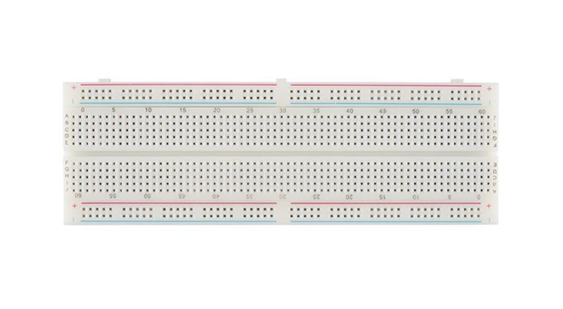
It’s a rectangular board with numerous holes arranged in a grid pattern, typically with metal clips or sockets beneath the holes to hold electronic components securely in place.
If you want to learn breadboard, see our article:
To test or build the electronic circuit, hobbyists, students, and professionals use the breadboard. The breadboard doesn’t need any soldering for a secure connection.
One of the key advantages of the breadboard is it is a reusable tool. Components can be inserted or removed easily and it is also very helpful for fast iteration and transition during circuit design.
Understanding DC voltage
DC voltage stands for Direct Current voltage. It refers to the constant voltage produced by a direct current (DC) power source, where the electric charge flows consistently in one direction.
In a DC voltage, the polarity (positive and negative terminals) remains constant over time.
It is beneficial in applications that need constant electrical energy, such as electronic circuits, electric cars, and telecommunications networks.
In certain applications, the DC voltage has to simplify the circuit design, lower the electromagnetic interference, and provide better control of the circuit performance.
DC voltage measurement on breadboard
Measuring DC voltage on a breadboard typically involves using a multimeter (DMM).
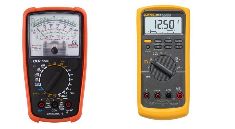
The digital multimeter is a versatile tool used to measure various electrical parameters like current, voltage, resistance, and capacitance. It is also useful in testing different components and circuits.
It has two types: Analog and digital multimeter. The main difference between these two is its display. The digital multimeter has an LCD screen and the analog has a needle that points toward measured results.
Here’s a general step-by-step guide on how to do it:
1. Turn on the multimeter
Take out your multimeter and thoroughly check for any damage. Press the ON button and Turn the multimeter ON for measurement.
2. Connect the test probes
Now connect the test probes to the multimeter. The multimeter typically comes with two test leads – a red one for positive and a black one for negative.
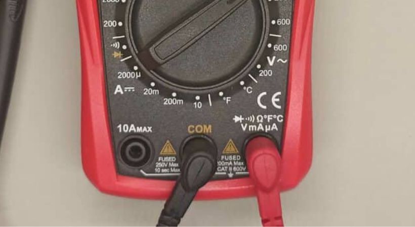
Insert the red test lead into the “VΩmA” (Voltage, Ohms, and milliamps) socket and the black test lead into the “COM” (Common) socket.
3. Test the multimeter
Short and open circuit tests can be performed to check whether the multimeter is working fine or not. Set the multimeter to the resistance mode.
For open circuits leave the test probes untouched, if the multimeter shows “1” or “OL” it means the multimeter is good.
By touching the probes of the multimeter with each other and multimeter displays zero resistance, so the meter also passes the test for short circuits.
You can also check our detailed article on testing multimeters:
4. Set the multimeter
Set the multimeter to the appropriate DC voltage mode. Most multimeters have a dial or buttons to select the voltage mode.
The DC voltage on the multimeter is represented by V with two straight lines above it, one dotted and one solid.
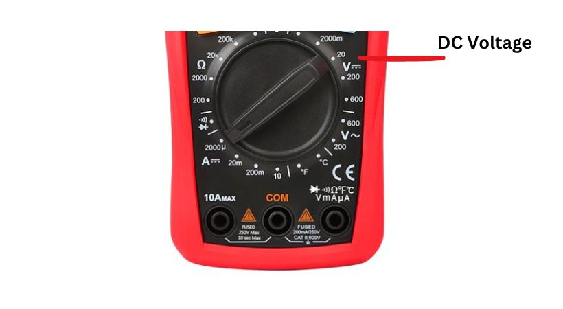
Now if you are using a manual range multimeter you also have to select the range of DC voltage you’re measuring.
Choose a range that is higher than the expected voltage to get the most accurate measurement. For example, if you expect the voltage to be around 5 volts, you might choose a 20V or 30V range.
The step of selecting the range can be skipped if your multimeter is auto-range. The auto-range multimeter selects the range automatically.
5. Connect the probes to the breadboard
Set the multimeter to the DC voltage mode and select the range if needed. If you want to measure the voltage across the components.
So place the test lead on the component in the circuit where you want to measure the voltage. The below picture shows the voltage measurement across the resistor.
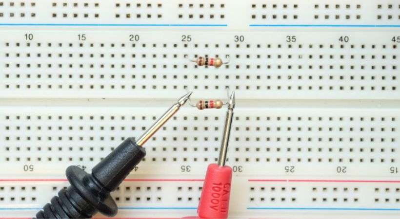
Remember that some components like LED have polarity so connect the multimeter correctly. Ensure that the red lead is connected to the point with a higher potential (positive) and the black lead to the point with a lower potential (negative or ground).
If you want to measure the voltage across a junction or nodes, you just have to find the reference or ground of the circuit and connect the multimeter across it.
For components to connect in series, you have to connect one test probe to the start component and the other probes to the last or extreme of the circuit component.
These are some ways you can measure voltage across different component configurations.
6. Read the measurements
Once the test leads are connected, the multimeter will display the measured DC voltage on its screen.
If the voltage is within the selected range, you’ll get an accurate reading. If the voltage exceeds the selected range, you’ll need to adjust the range setting on the multimeter and re-measure.
Remember the above range issue is for manual range multimeter if you have an auto-range multimeter the multimeter will display the results straightforwardly.
Best practices
To ensure accurate and reliable DC voltage measurements on a breadboard, consider the following best practices:
- Always use high-quality testing probes to create safe and reliable connections.
- Double-check the polarity of the test leads and ensure correct placement on the breadboard.
- Avoid excessive movement or disturbance of the test leads during measurement to prevent fluctuations or false readings.
- Take multiple measurements to ensure that the reading provided by the multimeter is correct.
- Exercise caution when working with live circuits, and always follow proper safety procedures to minimize the risk of electric shock or injury.
Conclusion
Measuring DC voltage on a breadboard is a fundamental skill for anyone involved in electronics prototyping and circuit design.
By understanding the principles, tools, and techniques involved, enthusiasts and professionals alike can effectively measure the DC voltage.
The multimeter is the tool used for measuring DC voltage, all you have to do is select the DC voltage mode and range and you are ready for the voltage measurement.
Connect the probes of the multimeter across the point where you want to measure voltage and after a few seconds the multimeter will display the results.
You can respect the process for different components in the circuit to ensure they are working accurately.
Measuring DC voltage on a breadboard opens up new avenues for exploration and creativity in the field of electronics.
I hope this article will help you in measuring DC voltage while you are working on any of your projects.
Other useful posts:
