Continuity using multimeter (Guide, 2025)
Continuity is the term used to describe the presence of a complete path for current to flow between two points in a circuit.
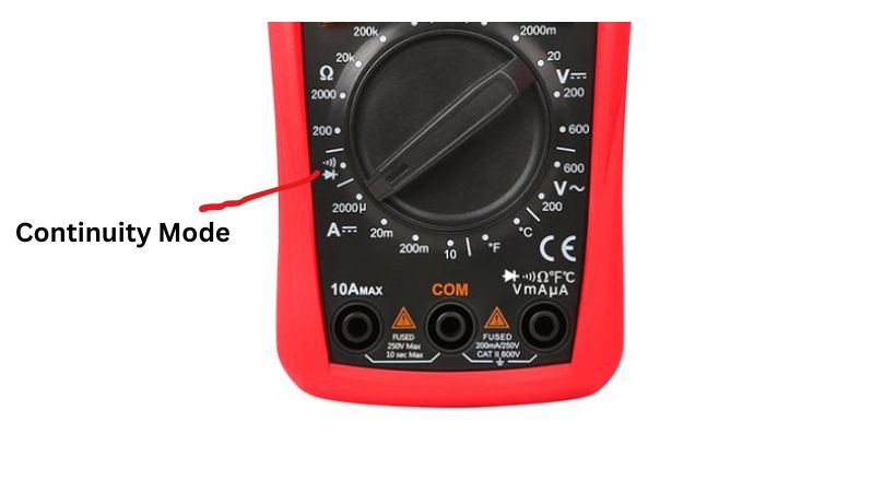
A multimeter is used to check the continuity of a circuit or component. The continuity is represented by a diode sign or sound wave sign. Set the multimeter to continuity mode, Connect the probes across the circuit points or component lead where you want to check the continuity, if the circuit path is complete the multimeter will produce a beep sound and if not, there will be no sound. After completing the test turn off your multimeter.
In this article, we’ll discuss the concept of continuity using multimeter and provide a comprehensive guide on how to check continuity using a multimeter.
What is continuity?
Continuity, in the context of electrical circuits, refers to the presence of a complete path for current flow between two points in a circuit.
When there is continuity between two points, it means that there are no breaks, gaps, or high resistance points in the path that would prevent the current from flowing freely.
Continuity means the circuit is closed and has a closed path for current flow. If there is a gap or breaks, the circuit is considered open, and there will be no path for current flow.
Continuity testing is the technique used to check the continuity of the electrical signal. This is typically done using a multimeter with a continuity testing function.
During the continuity testing, a multimeter sends a small current to the circuit and measures the resistance.
If there is low resistance (ideally close to zero ohms), the multimeter emits a beep or displays a signal indicating continuity.
However, if there is high resistance or an open circuit, indicating a break in the path, the multimeter will not indicate continuity.
Let’s discuss how can you check the continuity using multimeter in the circuit.
Check continuity using a multimeter
Here’s a step-by-step guide for conducting checking continuity using multimeter:
1. Set the multimeter
The first step is to check continuity using multimeter to take out multimeter and check for any damage or broken parts.
Also check the testing probes, if they are in good condition or not and are capable of performing the continuity testing.
2. Insert the testing probes
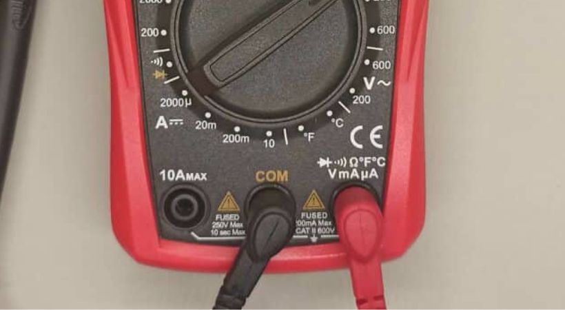
Insert the testing probes of the multimeter in the recommended jacks.

Insert the black probe in the COM jack of the multimeter and the red probe in the VΩ jack.
3. Select the mode
Select the continuity testing mode. This mode is usually denoted by a symbol resembling a sound wave or a diode with sound waves.

Some multimeters have a dedicated button to activate the continuity function of the multimeter. Make sure to press that button before starting testing.
Refer to the multimeter’s user manual for instructions on selecting the continuity mode.
4. Probe verification
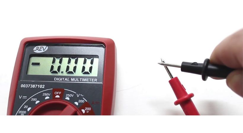
To test the multimeter and probes touch the two multimeter probes together.

The multimeter should emit a beep or display a low resistance reading indicating continuity. This step verifies that the multimeter is functioning correctly.
5. Ensure safety
Safety should always be a priority when working with any electrical and electronic circuit. So Before proceeding, ensure that the power to the circuit or component under test is turned off to prevent accidents or damage.
6. Probe placement
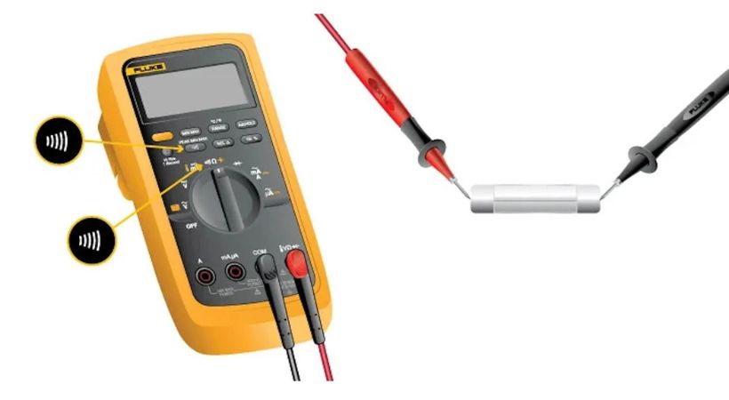
Now it’s time to connect the probes of the multimeter across the point of the circuit or component or a device where you want to test the continuity.

Place one probe of the multimeter at one end of the path you want to test for continuity and the other probe at the opposite end.
For instance, if testing a wire, place one probe at one end of the wire and the other probe at the other end.
7. Check for continuity
With the probes in place, observe the multimeter’s display. If there is continuity (i.e., a complete path for current flow), the multimeter will emit a beep or display a reading indicating low resistance.
If there is no continuity (indicating an open circuit), the multimeter will not emit a beep or will display a high resistance value.
8. Turn off the multimeter
You can repeat the same process multiple times but after that turn off the multimeter to conserve battery power and ensure safety.
Safety precautions
To minimize the electrical hazard and ensure personal safety when performing continuity testing, it is essential to follow safety precautions.
- Always ensure the power to the circuit or components being tested is turned off before performing continuity testing.
- Wear appropriate personal protective equipment, such as insulated gloves and safety goggles, especially when working with potentially energized circuits.
- Before using a multimeter, check it for any potential damage such as broken probes or cracked insulation.
- Ensure that the multimeter is set to the continuity testing mode.
- After completing the testing process, always remove the probes in reverse order. The red probe first and the black second.
By adhering to these safety precautions, individuals can conduct continuity testing using a multimeter safely and effectively, minimizing the risk of accidents while ensuring accurate and reliable results.
Continuity testing importance
There should be a closed path for the current to flow so continuity holds paramount importance in the realm of electrical engineering and maintenance.
Here are the reasons why checking continuity using multimeter is so essential.
1. Electrical system functionality
For the proper functionality of electrical systems, continuity is the fundamental concept.
The components, devices, and conductors in the electrical circuit should form the complete path for the current to flow. The break in the path can affect the flow of the current and can lead to malfunction or failure of the system.
So the continuity testing, guarantees that electrical signals and power can traverse through the circuit unimpeded, enabling devices to operate as intended.
2. Safety consideration
Continuity testing is closely associated with electrical safety. Faulty connections, broken wires, or open circuits can create hazardous conditions, such as electrical shocks, fires, or equipment damage.
By verifying and testing the continuity, technicians or beginners can identify potential safety risks and take corrective actions to mitigate them.
Regular continuity testing is essential for maintaining a safe working environment and preventing accidents or injuries caused by electrical faults.
3. Troubleshooting
Continuity testing is an indispensable concept for troubleshooting electrical circuits, components, or devices.
Technicians and hobbyists rely on continuity testing when the devices or systems malfunction to locate or identify broken or faulty components.
By systematically checking continuity at different points within the circuit, technicians can isolate the problematic area and identify the specific component or connection causing the issue.
4. Maintenance
For prolonged lifespan and reliability of electrical equipment, regular continuity checks are integral to preventive maintenance.
By periodically verifying continuity in circuits, connectors, and conductors, maintenance personnel can detect early signs of deterioration or wear.
Incorporating continuity testing into maintenance schedules enhances equipment reliability and reduces overall maintenance costs.
Conclusion
Continuity means the complete path for the flow of the current. If there is no complete path in the circuit the current will not flow and the circuit will not perform as intended.
We can test the continuity using multimeter of the circuit. The multimeter used for continuity testing is a simple process.
Follow the following steps to test the continuity of your circuit.
- Turn on your multimeter.
- Insert the testing probes in the jacks
- Select the continuity mode.
- Connect the probes of the multimeter across the points where you want to perform the continuity test.
- If the multimeter beeps, it means there is continuity in the circuit.
- If not, it means the circuit is broken and the current is not flowing.
These are the simple steps to follow for testing. checking Continuity using multimeter is an essential aspect of electrical maintenance and troubleshooting, ensuring the integrity and functionality of circuits and components.
I hope by following the steps provided in this guide you can perform continuity tests confidently and efficiently.
Thank you…
Other useful posts:
