
Resistors are components in electronics to limit the flow of current in the circuit. To connect resistors correctly in the circuit, understanding their pin configuration becomes crucial.
Resistors are two types: fixed and variable resistors. The fixed resistor has two terminals and it can be connected in any orientation. On the other hand, the variable resistor is the type of resistor that allows us to change its resistance so it has three terminals. To find pins of variable resistor a multimeter and component tester can be used.
This article will guide beginners in understanding resistor pin configurations and how to use them effectively in circuits.
Resistor pin configuration
A resistor is an electronic component that resists the flow of electric current, causing a voltage drop. It’s used in various electrical and electronic circuits to control current flow.
In the circuit, a resistor is represented by zig-zag lines or by a rectangular box with two terminals extended from it.
The resistor has different bands that tell the value of the resistance of the resistor. There are two types of resistors and each one has a different pin configuration.
It is crucial to understand the pin configuration of the resistor in order to connect it correctly. You can tell which terminal needs to be connected to the power source and which one to the ground by looking at the pin configuration.
Let’s see the different types of resistors and understand their pin configuration.
Fixed resistors
The fixed resistor is the type of resistor in which we can’t change the resistance. It is a two-terminal component.
Physically resistors look like cylinders in shape. The fixed resistor is a non-polarized component, meaning there is no positive or negative terminal. You can connect them in either direction in the circuit.
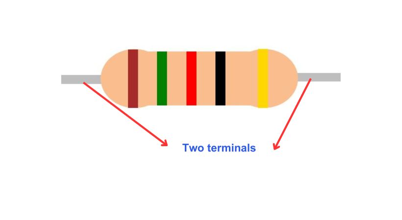
Fixed resistor has two pins (leads), one on each end of the cylindrical body. The pins of the resistor can be bent to fit into the holes of a breadboard or soldered onto a printed circuit board(PCB).
In simple words, for a fixed resistor, you don’t have to worry about its pins while connecting it to the circuit.
Variable resistors
Variable resistors, also known as potentiometers, are essential components in electronics that allow for adjustable resistance.
It is the type of resistor whose resistance can adjust according to our needs.
It consists of a resistive element, a sliding contact (wiper) or some have a knob, by moving the wiper along the resistive element or turning the knob, the resistance between the pins changes, allowing for control over the current and voltage in a circuit.
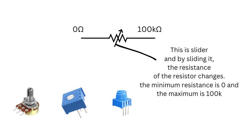
In the above example, the variable resistor has 0Ω minimum resistance and 100kΩ maximum resistance, so by moving the slider or knob the resistance of the resistor changes.
The variable resistor has three terminals. So to connect a variable resistor you have to understand its pin configuration.
There are two methods through which you can identify the pins to connect them to the power supply, load, and ground.
These are the following methods:
- Identification pins through a multimeter
- Identification pins through components tester
Let’s discuss both methods in detail.
1. Using a multimeter
A multimeter is a fundamental and easy-to-use measurement tool in electronics. It is used to measure current, voltage, resistance, and capacitance.
Multimeters can also be used to find the pin configuration of the variable resistor. To find the pin configuration of the variable resistor you must have a high-quality multimeter.
First, take out your multimeter and variable resistor. Now follow the following steps:
- Turn the multimeter knob to the resistance mode, which is normally represented by Ω sign.
- Connect the two probes of the multimeter to the any of two pins of the variable resistor.
- Start from the left to right side.
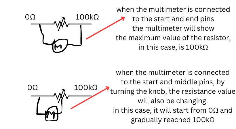
- Now turn the knob of the variable resistor, if the value on the screen changes the pin is slider terminal, and if not then it is fixed terminal.
2. Using component tester
The next is a component tester, a device used to find if the component we connect in the circuit is good or bad.
The multimeter just helps in identifying the pin, but the component tester along with pin configuration also tells us whether the component is good or bad.
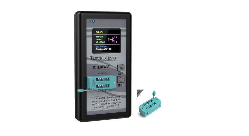
Select a high-quality component tester, and follow the following steps to test the variable resistor.
- Turn on the tester.
- Take your variable resistor and plug in the pins of the resistor into the sockets of the tester.
- After putting the resistor, press the test button.
- The tester will display the exact pin configuration of the variable resistor.
This is how you can find the pin configuration of the variable resistor along with its quality when connecting it to the circuit.
Conclusion
Understanding the pin configuration of resistors and variable resistors is crucial for designing and troubleshooting electronic circuits.
As a beginner, you may not know how to find the pin configuration of fixed and variable resistors before connecting them.
A fixed resistor is a type of resistor that has fixed resistance. It is a simple two-pin resistor. The fixed resistor can be connected to any orientation as it doesn’t have positive and negative terminals.
On the other side, the variable resistor is three terminal components, its resistance changes when we move the knob or slider.
To connect the variable resistor correctly we have to find its pin configuration. Two methods can be used:
- Using a multimeter
- Using a components tester
The multimeter just tells the pin configuration but the component tester not only tests the pin configuration but also tells the condition of the variable resistor if it is good or bad.
This is how you can find the pin configuration of the resistor, I hope it will be helpful.
Thank you and stay blessed…
Other useful posts: