
An LED is a polarized component so correct pin connections are essential for its functionality. Placing an LED on the breadboard is a very straightforward process.
All you need to do is to identify its pin configuration first. A component tester can also be used to help identify pins and tell if the LED is in good condition or not. After that place the LED leads into the two holes of the same row of the breadboard. Remember that wrong pin identification, not inserting the leads properly, and applying too much voltage can damage the LED.
In this article, we’ll discuss LED placement on the breadboard and the various mistakes a beginner can make.
Placing LED on breadboard
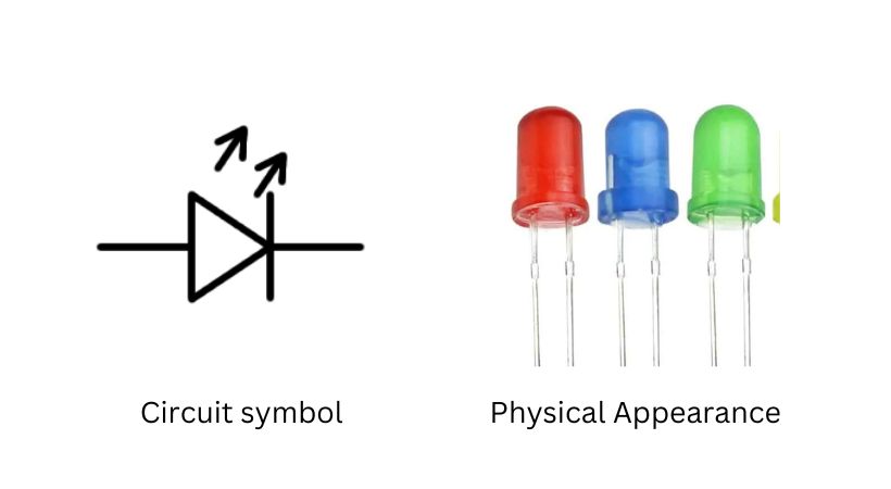
LED stands for light-emitting diode, it is the type of diode that emits light when the right amount of voltage is applied.
It is a two-terminal polarized component with anode and cathode. The LED comes in various shapes, sizes, and colors.
The following picture shows the circuit symbol and physical appearance of the LED.
They are used as indicator lights in various electronic devices. On your own mobile, you can see an LED light up when you connect it to the charger to indicate charging.
It must be difficult for a beginner to properly and correctly place an LED on the breadboard.
So don’t worry…
Let’s discuss how you can put an LED on the breadboard.
Process of putting an LED
Here is the step-by-step process of properly putting an LED on the breadboard to avoid any damage to the LED or other components in the circuit.
1. Understand breadboard
Understand the breadboard layout. It has two parts: the power railing and the main area where components will be connected.
The upper and lower part of the breadboard is a power railing where you will connect the power source to power up your circuit.
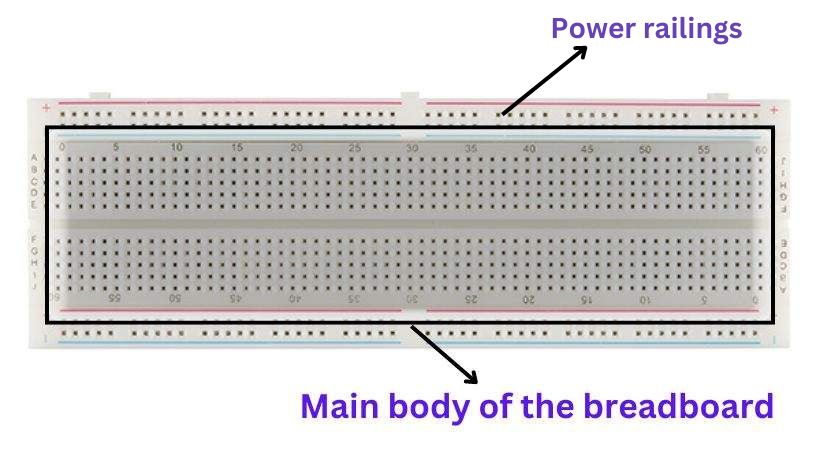
In the main area, you will connect different components logically to get the desired output. Remember the holes in the main area are connected vertically and holes in the power railing are connected horizontally.
2. Identify the LED pins
The LED is a polarized component so to make the correct connection and light up you have to identify the LED positive and negative pins.
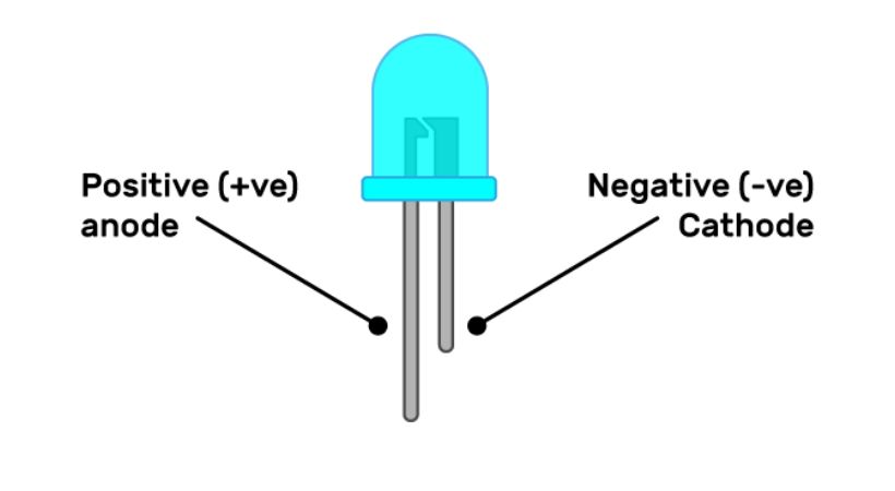
The easy way to identify the pins is to look at the LED pins, the longer one is the anode (positive) and the shorter is the cathode (negative).
If you are using a used LED look for the cut or flat side of the LED, that side is the cathode, and the other is the anode.
This is how you can find the LED positive and negative pins.
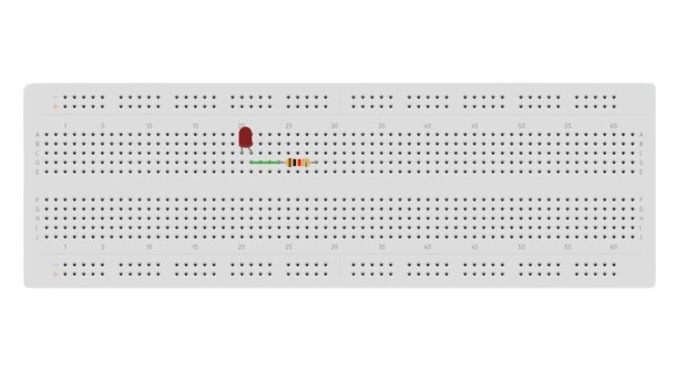
3. Insert the LED
Up till now, You have understood the breadboard and also identified the LED pins. Now it is time to insert the LED into the breadboard.
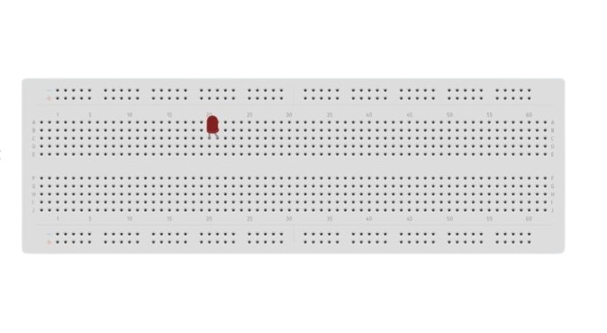
If the pin length is very long you can trim it a bit to make a strong connection with a breadboard. However, keep in mind which pin is cathode and anode.
Insert the anode in a hole of the row and cathode into another hole of the same row.
4. Add a resistor
To prevent the LED from burning out, a resistor is used to limit the current. The resistor value and connection depend upon the type of LED being used.
Most of the LEDs have a maximum voltage rating from 2 to 4 volts so applying greeted voltage without a resistor connection can damage the LED.
If the applied voltage is greater than the voltage rating of the LED, connect a recommended value resistor with the LED.
Insert one leg of the resistor into the hole of the column where the anode of the LED is connected.
5. Power supply connection
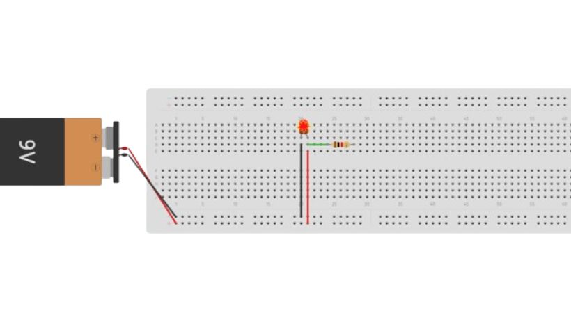
Use the jumper wires to connect the power supply to the LED circuit. Connect the negative (black) of the power supply to the cathode of the LED.
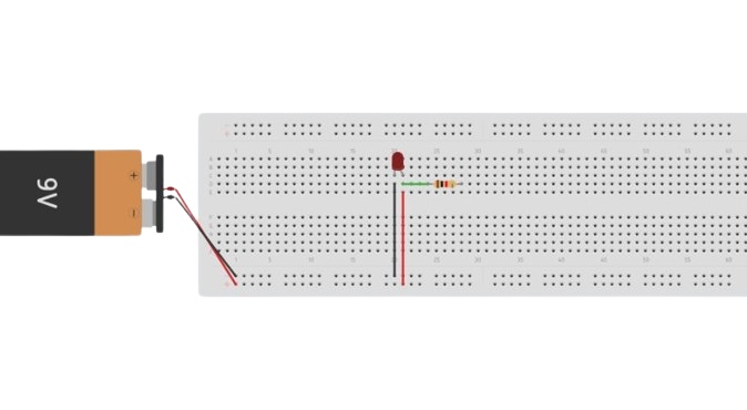
The positive of the power supply will be connected to the other end of the resistor. After the power supply connection, the LED will light up, if not then check the connections.
Common mistakes to avoid
When placing an LED on a breadboard, several common mistakes should be avoided to ensure the LED functions correctly and safely.
Here are the key mistakes and how to avoid them:
1. Wrong polarity identification
The first common mistake that you can make as a beginner is identifying the wrong pins of the LED. The pin which is an anode you identify it as a cathode.
Wrong pin identification means you will connect the power source in reverse which will lead to damage to the LED or can even burn it.
Keep in mind that the longer pin is an anode and the shorter pin is a cathode. Before connection check the pins of the LED again.
2. Improper connections
The loose connection can lead to inconsistent operation or even failure of the LED. Sometimes you don’t push the LED pins properly into the breadboard holes, so a good connection is not made.
Ensure that all components and LED are firmly inserted into the breadboard holes. Double-check that the jumper wires and component leads are properly connected.
3. Not connecting a resistor
Since the LED has a limited voltage rating, a recommended voltage must be provided across it; increasing the voltage will cause the LED to burn out.
If the applied voltage exceeds the LED voltage ratings, you have to connect the resistor to limit the voltage so that the LED doesn’t burn out.
The values of the resistor depend upon the applied voltage.
4. Connecting incorrect resistor value
Connecting a very low and high-value resistor is also a common mistake that can be made by a beginner.
Using a low-value resistor means it will still damage the LED by not properly limiting the current. On the other hand, using a high-value resistor means, that all applied is dropped across the resistor and the LED will not light up properly.
Ohm’s law can be used to calculate the resistor value.
R = Vsupply-VLED/ILED
Where “R” is the resistance, Vsupply is the applied voltage, VLED is the voltage drop across the LED, and ILED is the desired current for the LED.
Depending on the LED, the desired current of the LED ranges from 10 to 30mA. Make sure to connect the right value resistor across the LED.
These are some mistakes that should be avoided to prevent the LED and the whole circuit from the damaged.
Conclusion
LED is the basic electronic component that is part of almost all electronic circuits for indication purposes.
As a beginner, when you are designing your circuit on the breadboard the correct placement of the LED is essential for its functionality.
On the breadboard, the LED placement is very simple, all you have to do is understand the breadboard first and learn about its rows and columns connection.
The next thing is to identify the pin’s polarity of the LED, the long leg is an anode and the short leg is a cathode. Now place the pins of the LED into two holes of the same row of the breadboard.
If needed connect a resistor to the anode to prevent the LED from damaging. Try to avoid common mistakes like:
- Identifying incorrect pin polarity
- Not connecting a resistor
- Connecting a wrong-value resistor
- Not properly pushing an LED into the holes of the breadboard
While connecting an LED, keep these mistakes in mind and essentially connect the LED on the breadboard.
That’s it, this was all about placing LED on breadboard, I hope it will be helpful in your project.
Thank you and stay blessed…
Other useful posts: