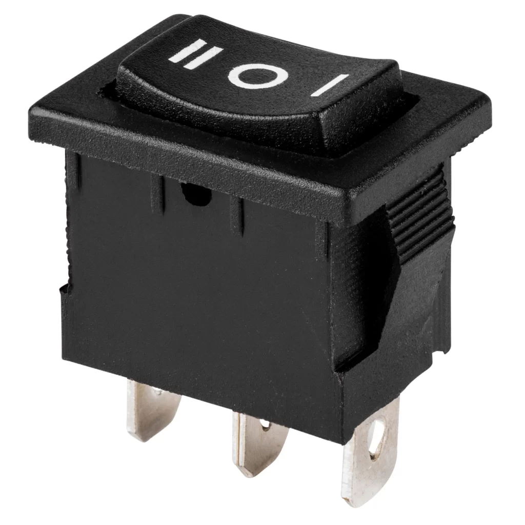
Switches are fundamental components in electronic circuits, used to control the flow of current. Identifying switches’ pin configurations is crucial for correctly integrating them into circuits.
Various methods such as referring to datasheets, visual inspection, and multimeter use are useful for switch pin configurations. A datasheet is the most reliable method for pin configuration as it tells the correct pin information, examining physical layout and labels also helps in pin identification. Using a multimeter to test the continuity between pins helps identify their functions.
Let’s discuss switches pins configuration in detail in this article so that you can connect the switch correctly in the circuit.
Switches
To control the flow of the current in the circuits, switches are used. Switches are just like an on and off button for the circuit.

When the switch is on, the circuit is closed so the current will flow, and when the switch is off the circuit is open, and no current will flow.
There are various types of switches such as single-pole single-throw (SPST), double-pole double-throw (DPDT), etc. Each switch has a different pin configuration.
The correct configuration of the switches is essential for proper switch connecting in the circuit.
Let’s talk about the different methods that will help in the switch pin configuration.
Switches pin configuration
The following is an explanation of how to determine switch pin configurations for different kinds of switches:
1. Referring to the datasheet
The datasheet is like an information book related to the component you are using. Understanding the datasheet is the most reliable and authentic method for pin configuration.
For SPST switches the pin configuration doesn’t matter but for switches like DPDT, and SPDT pin identification is necessary.
The datasheet offers a comprehensive blueprint with a pinout diagram that makes the purpose of each pin clear.
Find the datasheet of the switch you using and check its pin configuration.
2. Visual inspection
Visual inspection is another method for switch pin configuration.
Follow the following steps for this method.
- Take the switch
- Examine the physical layout and labeling on the switch.
- Some switches have pins labeled with their function such as “C” for common, “NO” for normally open, and “NC” for normally closed.
- In simple switch pin configuration is easy as it has one input and one output.
- Examine the switch carefully with multiple inputs and multiple outputs.
Visual inspection is most effective for common switch types. If markings are unclear or absent, proceed with caution.
3. Use of multimeter
The trusty multimeter can be a helpful tool for identifying pin configurations, but it’s best suited for basic DPDT and SPDT switches.
The multimeter is the tool that is used to measure the current, voltage, and resistance in the various circuit components. It is also used to test the continuity of different components.
For switch pin configuration, the resistance mode of the multimeter will be used. The single-pole single-throw pin configuration is simple, it has one input and one output.
Now let’s discuss how you can configure the pins of the switch.
Single-pole single-throw (SPST)
- This type has two pins.
- So without the multimeter usage, one pin is for input and one is for output.
- If you connect multimeter probes across two pins, in the “off” position, the resistance should be infinite (open circuit).
- In the “on” position, the resistance should be close to zero (closed circuit).
Single-pole double-throw (SPDT)
- This type of switch has three pins.
- Common, normally open, normally closed.
- Labeled the pins like A, B, C
- Now set the multimeter to resistor mode and connect the probes to it.
- Connect the black probe to the common pin and the red probe to either of the two pins.
- The resistance between the common pin and one of the other pins should be close to zero, so it is a normally closed pin.
- while the resistance between the common pin and the other pin should be infinite, this is a normally open pin.
Double Pole Double Throw (DPDT)
- It has six pins, three on one side and three on the other side of the switch.
- This switch is like having two SPDT switches, one SPDT on one side and the other switch on the other side.
- This process of pin identification for this switch is the same as we did for SPDT. follow the same procedure as we did above.
Using the resistance mode on a multimeter is a straightforward and effective method to identify the pin configurations of various switches.
By systematically measuring and documenting resistance readings, you can accurately determine which pins are connected in different states.
Conclusion
To control the flow of the current in the circuit, the use of switches is the only option. Switches come in different orientations and pin configurations.
So Identifying the pin configuration of switches is essential for their proper integration into circuits.
The methods like
- Datasheet usage
- Visual inspection
- Use of multimeter
Referring to the datasheet is a simple and reliable method to tell specific pin functions. Some switches have labels or markings on them which help in the visual identification of pin functions.
The last method is the use of a multimeter. The multimeter is the most useful tool in electronic circuits. It helps in measuring current, voltage, and resistor along with these it also finds the pin configurations of some components.
Use the resistance mode of the multimeter to find the pin configuration of the switches. The SPDT and DPDT are the switches that need pin identification as it has multiple inputs and multiple outputs.
Keep in mind that identifying switch pins successfully requires a combination of the appropriate equipment, expertise, and caution. I hope this article helps you with the pin configuration of switches.
That’s it for switch pin configuration.
Thank you and have a blessed life…
Other useful posts:
