
Understanding the breadboard layout is crucial for anyone who loves to work with electronic circuits.
The breadboard has two main parts: the power rails and the main body. Power rails, at the top and bottom, handle power distribution. The main body connects electronic components and features small gaps in the center for placing integrated circuits.
In this article, we will explain the layout of a breadboard and provide tips for utilizing its layout.
Breadboard parts and functions
Breadboards are great for experimenting with different circuit designs. Before understanding the breadboard layout, let’s discuss what is the breadboard and how it works first.
In electronics, a breadboard is an essential tool for testing, developing, and experimenting with circuit designs without the need for soldering.
It offers a platform on which electrical parts are simply put and linked to make circuits fast and effective.
A breadboard typically consists of a rectangular plastic board with a grid of holes arranged in rows and columns. These holes are used to insert electronic components such as resistors, capacitors, integrated circuits, and wires.
Now you have a little bit idea of what is a breadboard and how it works. Let’s see the layout of the breadboard and how and where you can connect the components and power source.
We can divide the layout of the breadboard into two: The power rails and the main area.
1. Power rails
The columns and rows are present in the power rails for the connection of the power sources such as battery, or power supply.
At the upper and bottom of the breadboard, there are rows of holes, these rows are called the power rails of the breadboard. The power rails are also called bus strips sometimes.
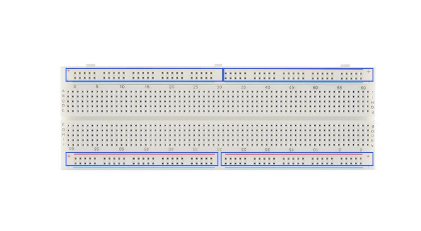
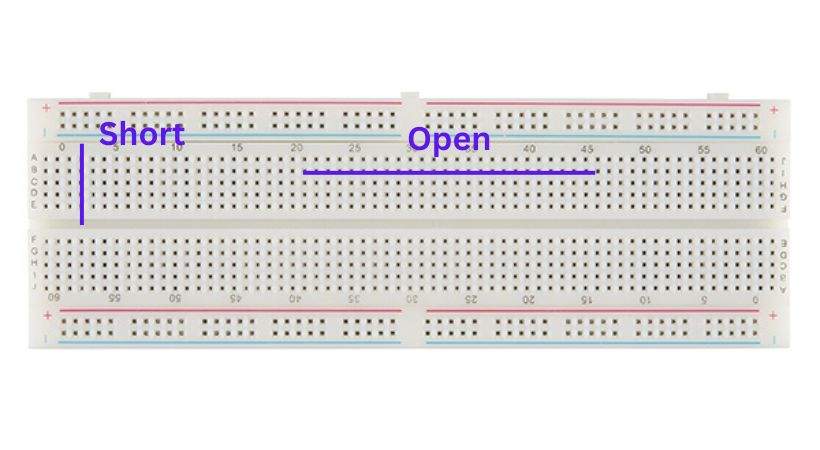
The holes of power rails are connected horizontally means when you connect the positive terminal of the batter then the whole row will have a positive voltage of the battery so you can take the connection from any hole of the row.
The power rails are specified where the positive and negative of the battery should be connected. The red rail is typically designated for positive voltage, often labeled as “+”, while the blue rail is used for ground, labeled as “-“.
It’s important to connect your power source’s positive terminal to the red rail and its negative terminal to the blue rail to ensure proper functionality.
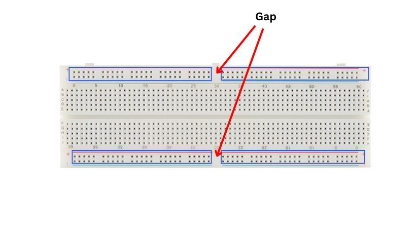
There will be some projects where you will need various voltage sources so the breadboard allows you to connect multiple power sources to operate or test your circuits. The power rail of the breadboard is divided into four portions.
Each power rail is split into two sections horizontally, often with a gap in the middle. This allows you to easily connect multiple components or power sources without causing short circuits.
If you connect one power source to the portion 1 of the power rail then the gap doesn’t allow the voltage to connect to the portion 2. Thus, you can attach a separate power source to section 2 that has a different voltage.
2. Main connection area
Between the power rails of the breadboard, there is an area that has numerous holes that are arranged in columns and rows. This is the area where you can build your circuit.
The main area is labeled from A to J, these labels indicate that components can be inserted in this area of the breadboard.
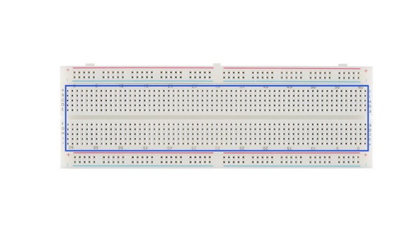
It’s a grid of holes arranged in rows and columns. Each column typically also has five holes. The holes are placed so you can insert electronic components and connect them using jumper wires easily.
The holes of the breadboard where you want to connect different components are connected vertically which means if you connect the component in any of the two holes then the entire column will be the extended version of the connected component.
Let’s understand this with an example.
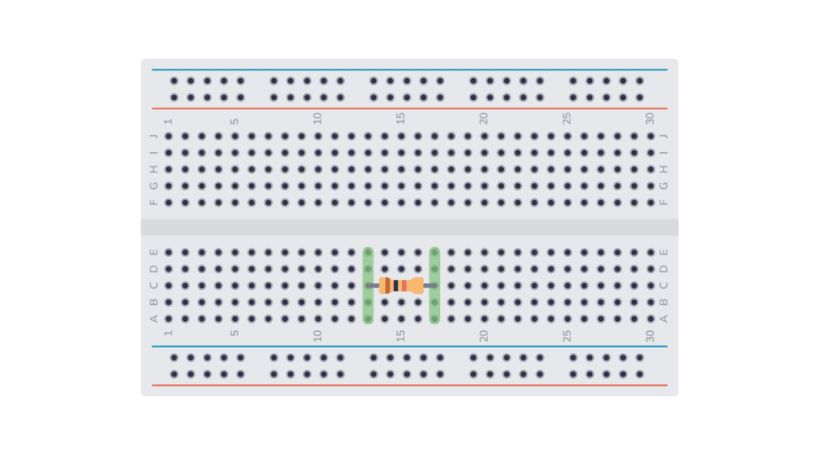
As you can see in the above picture, a resistor is connected to the breadboard.
The columns where the terminals of the resistor are connected now if you connect the other component in the same column it means you connect the component to the terminal of the resistor.
This is what I meant by the columns being connected vertically so when creating a circuit keep this point in mind.
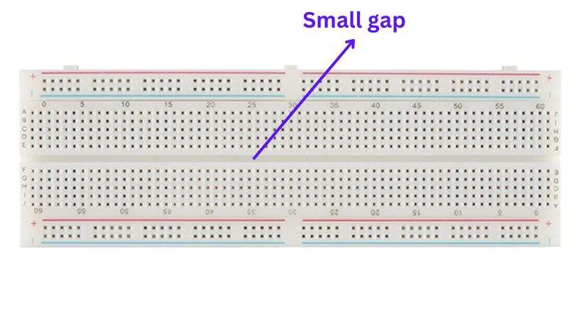
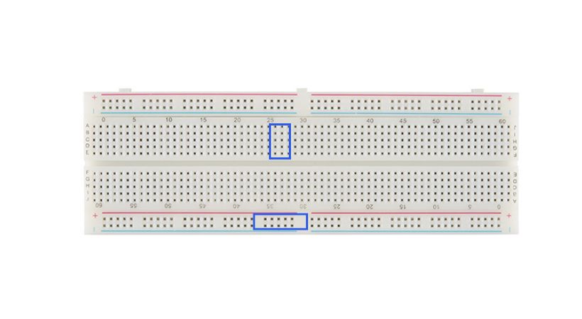
There is one more thing about the breadboard, when you look at the breadboard you can see that the main connected area starts from A, B, C, D, E, and again starts from F, G, H, I, J. Between these portions there is a small gap.
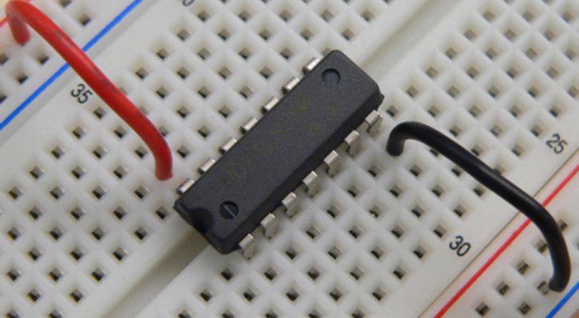
This small gap is used to connect an integrated circuit (IC). the columns in which the IC is placed are not the extended version of the IC pins and you can connect the components to the pins of the IC using the columns.
If the IC is connected in the upper and lower portion of the main area, it means you have short IC legs and the IC can be damaged due to overheat.
So in the upper and lower the different components can be connected and IC should be connected between E and F.
Tips for breadboard
Here are some technical tips to keep in mind while connecting components on breadboards:
- Ensure that you insert components correctly into the breadboard to avoid damaging them or causing circuit malfunctions.
- Keep the leads as short and straight as possible while still allowing them to reach their respective holes on the breadboard.
- Avoid overcrowding the breadboard by spacing out components and wires appropriately.
- Identify where each component will be placed and how they will be interconnected. This can help streamline the assembly process and reduce errors.
- Double-check all connections on the breadboard to ensure they are inserted into the correct holes and are making proper contact.
By following these tips you can effectively connect components on the breadboard and build reliable and functional circuits for your electronics projects.
Conclusion
To build a circuit and do iteration in the circuit connection then a breadboard is the must tool to have in your lab.
Breadboard is a tool that allows you to connect different components and build and test the circuit without soldering.
The breadboard has various holes that are arranged in rows and columns. In these holes, different components are inserted.
We can divide the breadboard layout into two parts: the power rails and the main component connection area. The upper and lower portion of the breadboard are called power rails and they are labeled as “+” and “-”.
Between the power rails, there is a main components connection area.
As the main area’s columns are connected vertically, connecting a component to a column where another component has already been connected indicates that you are connecting the component to its terminal.
Make sure you connect the components correctly and make secure connections for a reliable and effective circuit.
**This was all about the breadboard parts and functions. You can keep learning by exploring how to power a breadboard safely and properly.