
Circuit diagram into breadboard prototype (Guide, 2025)
Creating a breadboard prototype from the circuit diagram is fascinating. Circuit diagram is a graphical representation of electronic circuits.
An exciting stage in understanding electronics is converting a circuit into a prototype. Understand the circuit schematic, gather the necessary tools such as breadboard, jumper wires, electronic components, and a multimeter, plan, and place components accurately, and methodically make connections to ensure a functional and organized prototype.
This article will discuss a step-by-step process to help you convert a circuit diagram into breadboard prototype.
Circuit schematics
A circuit schematic is a graphical representation of the electronic and electrical circuits, it symbolically represents different components such as resistors, capacitors, diodes, transistors, and integrated circuits.
The schematic serves as a blueprint for constructing and understanding the circuit, illustrating how current flows through the system and how different parts interact.
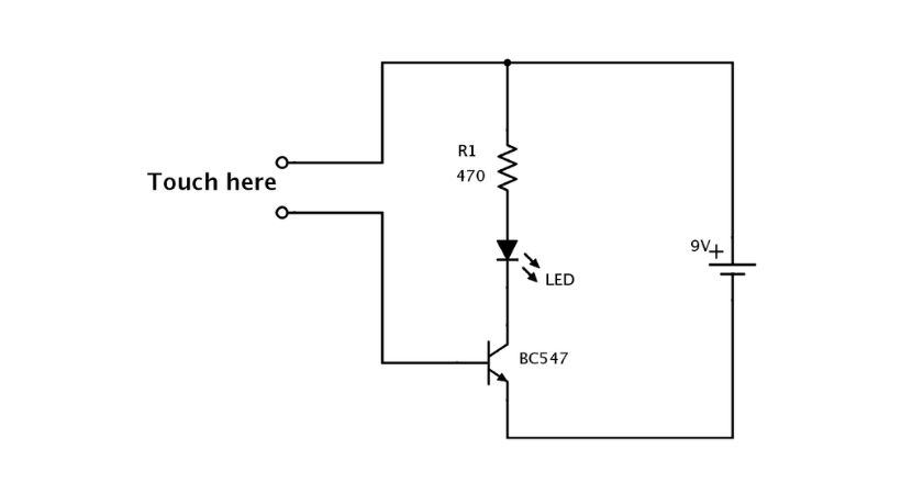
The above picture represents a circuit diagram or circuit schematics of the touch sensor, in this circuit, the function of the LED is controlled with the touch of fingers.
It is an essential tool for engineers and hobbyists, enabling them to design, analyze, and troubleshoot circuits before physical assembly.
In simple words, the circuit schematic provides information to understand how the circuit works. You must read the circuit and understand the component symbols before building it.
If you want to learn more about circuit schematics, here is our article
What is a breadboard prototype?
We can call it the physical version of the circuit schematics, the breadboard prototype is a method used in electronics to build and test circuits quickly and efficiently without the need for soldering.

The above represents the breadboard prototype of the touch sensor circuit schematic.
Breadboard is a tool that helps in converting a graphical version of the circuit into a physical device.
A breadboard is a reusable platform with a grid of interconnected holes, into which electronic components like resistors, capacitors, transistors, and integrated circuits (ICs) can be easily inserted.
Breadboard prototyping is essential for both the learning and development phases, allowing designers to validate their ideas and ensure the functionality of the circuit schematic.
It required proper lab setup as various tools will be needed when working with circuits.
If you are curious about how can you set your lab for prototyping, read out article
This was a little explanation of circuit schematics and breadboard prototypes, now let’s discuss how can you convert a circuit schematic into a breadboard prototype.
Converting circuit diagram into prototype
Transforming a circuit schematic into a working prototype on a breadboard is an exciting step in bringing your electronic design to life.
Here we’ll discuss a step-by-step process of how can you convert a circuit diagram into a prototype with an example.
We will take the same example of the touch sensor in which we’ll control an LED with our fingers.
Let’s see the process…
1. Understand circuit schematics
The first step of converting circuit schematics is to understand the schematics and identify different component symbols that are connected in the circuit.
Let’s take the same example which we are discussing in the article and identify the components.
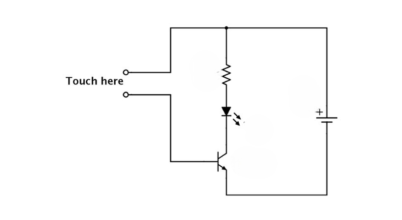
For the touch sensor, two wires are used. Now the zig-zag lines represent the resistor, the diode symbol with arrows outward shows an LED, after the LED the next symbol is for the transistor and the transistor is NPN as the arrow is outward from an emitter.
The last symbol is for the battery to provide power to the circuit. The components are identified.
It’s time to understand how they are connected. The transistor emitter is grounded as it is connected to the negative of the battery. The collector is connected to the cathode of an LED and the anode is connected to the one end of the resistor.
The two wires will be used for controlling the LED with finger touch, so the other end of the resistor is connected to one wire and then connected to the positive of the battery. The other wire is connected to the base of the transistor.
When you touch the two wires with a finger it will turn on the LED and after lifting the finger the LED will turn off.
Now move to the next step, gather the components.
2. Gather the components
Look for the components that are connected in the circuit schematics.
The following components you will need:
- Breadboard
- Multimeter
- 470Ω Resistor
- BC547 transistor
- LED
- 9V battery
- 9V battery clip
- Jumper wires
To identify LED and transistor pins and resistance values multimeter is useful.
3. Understand the breadboard layout
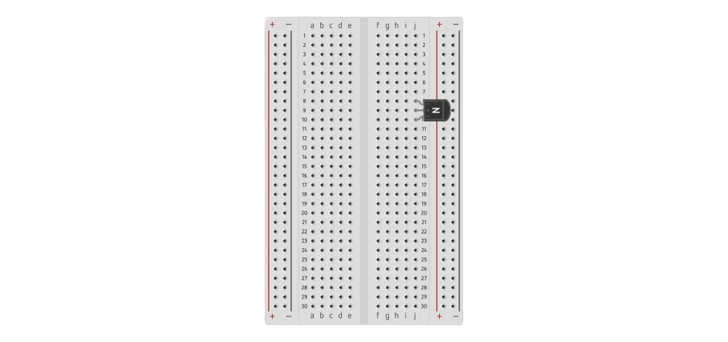
Understanding the breadboard layout is essential as you have to build circuits on it. So we can divide the breadboard into two parts: power railings and main components connecting area.
The upper and lower portion is called power railing, the holes are connected horizontally in this area. The portion is labeled with “+” and “-” to connect the positive and negative of the battery easily.
In the middle we have the main components connection area and holes in this area are connected vertically. By understanding the breadboard layout you will ensure clear and neat routing, avoiding unnecessary overlaps.
4. Identify component pins
Before placing components on the breadboard, understand it pin configurations. The resistor is a non-polarized component it doesn’t pin identification.
Components like LED and transistors need pin configuration to connect it properly. For LED the longer pin is anode (positive) and the shorter pin is cathode (negative).
For the transistor, you can use a multimeter or component tester.
You can also check out our article:
5. Placement of the components
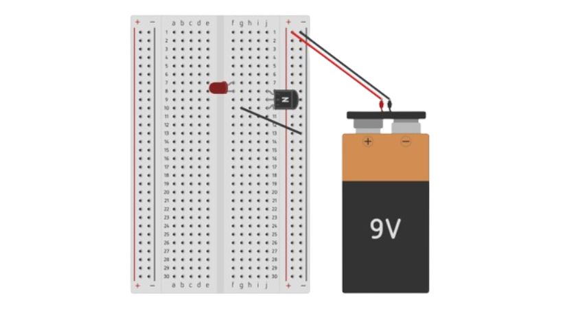
Place the components on the breadboard and make connections using jumper wires. Place the transistor on the main connection area of the breadboard.
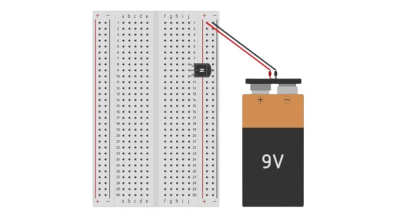
Connect the battery to the power rail of the breadboard. The positive of the battery should be connected to the positive of the power railing and the negative should be connected to the negative of the power railing.
The emitter of the transistor should be grounded and connect the LED cathode to the collector.
Connect the anode of the LED to the one end of the resistor and two wires place them on the breadboard.
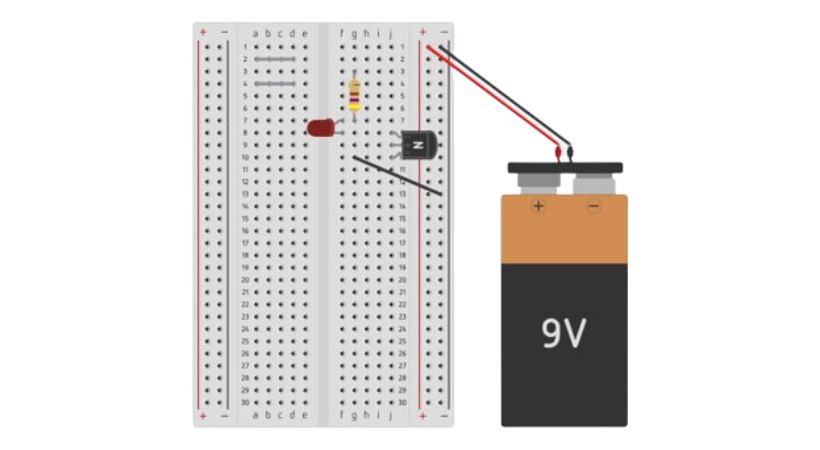
The base of the transistor should be connected to one wire and the other wire should be connected other end of the resistor. After the wire connection connect the resistor to the positive of the battery using a jumper wire.
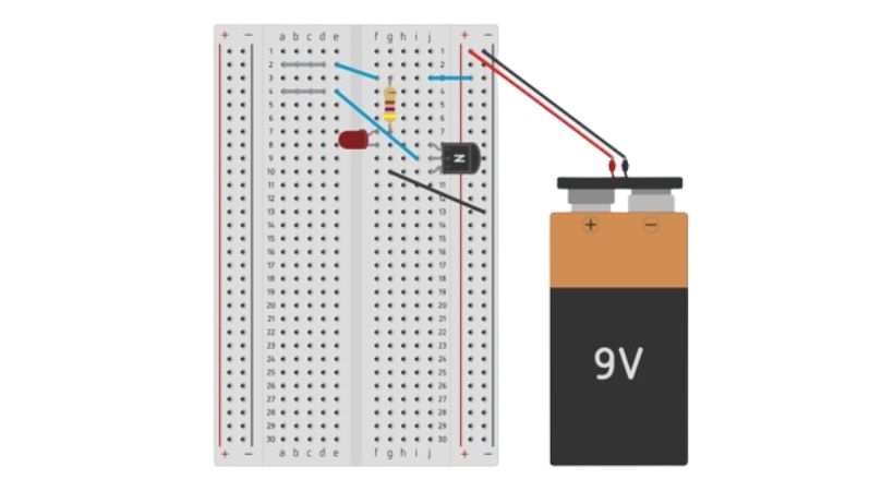
Now you convert the circuit schematic into breadboard prototyping. By touching the grey wires the LED will light up.
6. Double-check the connections
Before testing, verify the different connections.
If the circuit does not work as expected, turn off the power and check connections, component values, and orientation.
This is how you can effectively convert a schematic diagram into a working breadboard prototype, allowing you to test and iterate on your electronic designs.
Common mistakes
When converting a circuit schematic into a breadboard prototype, several common mistakes can occur, potentially leading to malfunctioning circuits or difficulty in troubleshooting.
Here are some of the key mistakes to watch out for:
1. Wrong component placement
Placing components in the wrong place may cause short circuits and can damage other components.
If you Insert ICs or other components with multiple pins into the wrong rows, leading to improper connections.
The placement of polarized components like LEDs, diodes, and electrolytic capacitors backward, can prevent the circuit from working or even damage components.
Understand the breadboard layout and identify the pin configuration of polarized components before connecting it.
2. Incorrect connections
Not properly connecting the power to the circuit and Forgetting to connect all necessary wires, resulted in an incomplete and malfunction of the circuit.
Misunderstanding how the breadboard power rails are connected, especially if the rails are split in the middle. Use two small wires and connect the split power railings.
Always double-check the connections and connect the power source correctly with the breadboard.
3. Component damage
Using incorrect component values, such as resistors with too low resistance, can cause overheating and damage.
Failing to use proper anti-static precautions when handling sensitive ICs and transistors. Properly understand the circuit schematics and note the component values for error-free circuit design.
4. Overcrowding
Sometimes we connect all components on a small portion of the breadboard which makes it difficult to troubleshoot and increases the likelihood of accidental shorts.
The Use of excessively long jumper wires, can cause signal interference and make the layout confusing.
Make sure to connect components at some distance and use the appropriate length of jumper wires.
Conclusion
Converting a circuit schematic into a breadboard prototype is an essential skill for electronics enthusiasts and professionals alike.
Circuit schematics is a graphical representation of electronic components connection and breadboard prototyping is physical connections of components.
This article has outlined the step-by-step process, from understanding the schematic to testing the final prototype.
You can guarantee a working and well-organized prototype by carefully organizing, precisely arranging components, and methodically connecting them.
Understand the common mistakes like components’ wrong placement, incorrect connections, damage to the components, and connecting various components in small places to avoid damage to the circuit.
Remember by practicing and paying close attention to details, you will become skilled at turning schematics into functional breadboard prototypes.
That’s it, this was all about how can you convert a circuit diagram into breadboard prototype. I hope you enjoy this article.
Thank you…
Other useful posts: