
Circuit schematics are the backbone of electronics engineering. They are the essential blueprints for designing, analyzing, and troubleshooting electrical and electronic systems.
The circuit schematic is the graphical representation of an electrical and electronic circuit. It tells the components and how they are connected in a circuit. The circuit schematic has standardized symbols that are used to represent components like resistors, capacitors, LEDs, transistors, etc. The schematic helps beginners, or engineers analyze the circuit behaviors, design new circuits, and troubleshoot the circuit.
In this article, we will delve into the basics of circuit schematics, and explore component symbols.
Circuit schematic
A circuit schematic, also known as a circuit diagram, is a graphical representation of an electrical or electronic circuit.
It uses standardized symbols to represent the various components and their interconnections within the circuit. In the above circuit, you can see that the battery, resistor, and LED are connected and each one has its symbol.
The circuit schematic also represents the details of the components like resistor or capacitor values, transistor number, etc.
The use of the circuit schematic is to give a clear way to understand how a circuit works, how it will be constructed, and if any issue arises how will you troubleshoot it.
In simple words, we can say
A circuit schematic is the structure and functionality of an electronic circuit, allowing engineers, technicians, and hobbyists to understand and analyze the circuit’s behavior.
A circuit schematic focuses on the logical connections between components rather than their physical placement.
This abstraction allows for a more clear and concise representation of the circuit, making it easier to understand and troubleshoot.
Importance of circuit schematic
Circuit schematics serve as the foundation for engineers or beginners to design, analyze, and troubleshoot a circuit. By providing a visual representation of the circuit, they can design a prototype effectively.
Here are details of why circuit schematics are so important.
1. Understand circuit behavior
The circuit schematic is essential for learning and understanding circuit behavior. It provides a visual representation of the circuit, which enables the engineer and beginners to visualize how the circuit will work and behave.
They study the component’s behavior and their interconnections. Through this engineers can grasp the overall functionality of the circuit and predict its behavior.
2. Design and prototyping
The engineers plan and simulate the circuit operation, all this possible due to the schematic diagram.
The schematic diagram allows to planning and design of the circuit layout and functionality before the physical circuit. It also helps in estimating the circuit cost.
It allows engineers to experiment with different configurations, select appropriate components, and optimize the circuit for performance.
3. Troubleshooting
Just imagine, you don’t have the circuit diagram of the circuit you are working on. Suddenly some problem arises with it and it behaves abnormally, what you will do?
The troubleshooting will become difficult without knowing how the components are connected.
The circuit schematic helps trace signal paths, identify faulty components, and pinpoint areas of concern within the circuit, speeding up the debugging process and reducing downtime.
4. Effective communication
Schematics serve as a common language for engineers, technicians, and other stakeholders involved in the design and development process.
You can share the circuit schematic and your issue with other experts if you’re having trouble understanding circuits so that they can fix the problem.
By giving team members a common representation of the circuit, they promote communication and enable productive idea-sharing, decision-making, and teamwork.
5. Advancement
The foundation for creativity and advancement in electronics engineering is provided by circuit diagrams.
Schematics promote innovation and growth across a range of industries, including consumer electronics and aerospace, by allowing engineers to test new concepts, refine existing designs, and investigate cutting-edge technology.
Symbols used in circuit schematic
Circuit schematics utilize a defined set of symbols to represent various electrical components and their interconnections.
These symbols help in producing a consistent and understandable representation of the circuit since they are used universally.
Some of the most commonly used circuit schematic symbols are as follows:
1. Resistors
The resistor is the part of every circuit. So the most used symbol of the resistor is a zig-zag line extended from both sides. The rectangular space and lines on both sides are the international symbol for resistors.
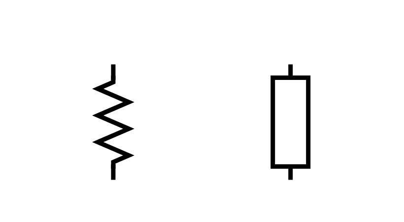
Above are the symbols of the resistor that are used in the circuit diagram. The symbols of variable resistors and potentiometers are different.
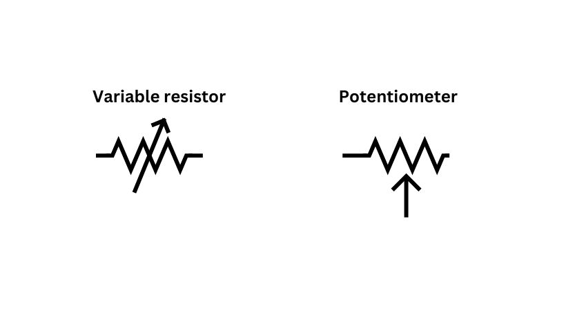
The variable resistor has an arrow above the zig-zag line and the potentiometer has an arrow pointing toward the zig-zag line.
2. Capacitors
The capacitor is an electronic component used to store energy. It has two types non-polarized and polarized each one has different symbols.
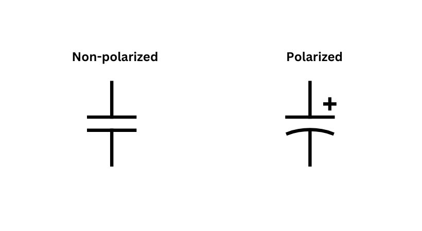
The non-polarized has parallel lines and lines extended on both sides. On the other hand, the polarized has one straight line and another curved line with lines extended on both ends.
3. Inductors
The inductor is a component that produces a magnetic field when current passes through it. The symbol of an inductor is like a coil.

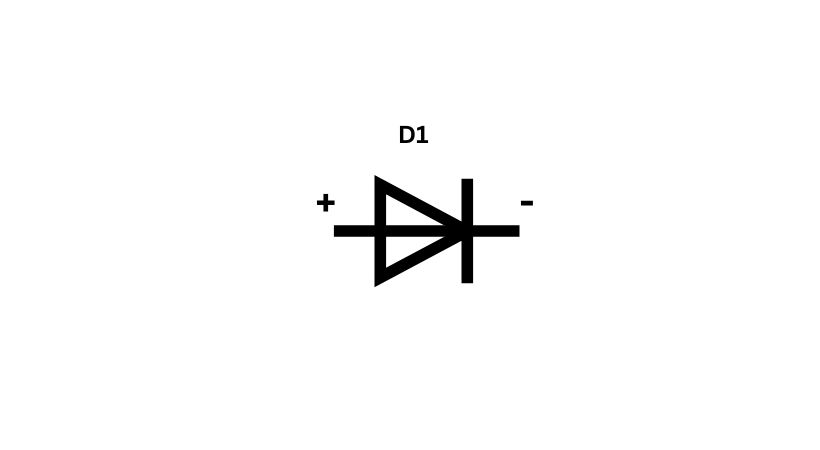
4. Diodes
The basic symbol of the diode is a triangle with a straight line. It is a polarized component so extended lines at both ends represent positive and negative terminals. The extended line from the straight line is negative and the line entering the triangle is positive terminal.
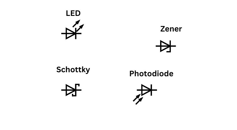
There are different types of diodes such as LED, photodiode, and Schottky diode, different symbols are used to show these types.
5. Transistors
The transistor, if we talk about BJT’s they are available in two configurations. The PNP and NPN.
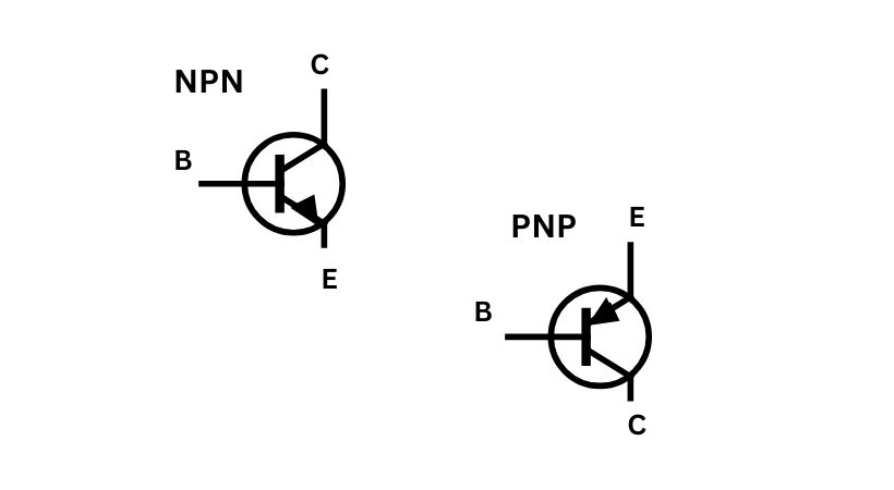
The transistor has three terminals, emitter, collector, and base. The arrow pointing away from the base is the NPN symbol and the arrow pointing toward the base is the PNP symbol.
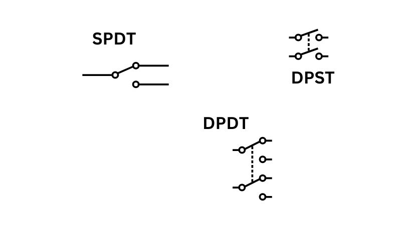
6. Switches
The different types of switches used in the electronic circuits. The most common type of switch is single-pole/single-throw (SPST).
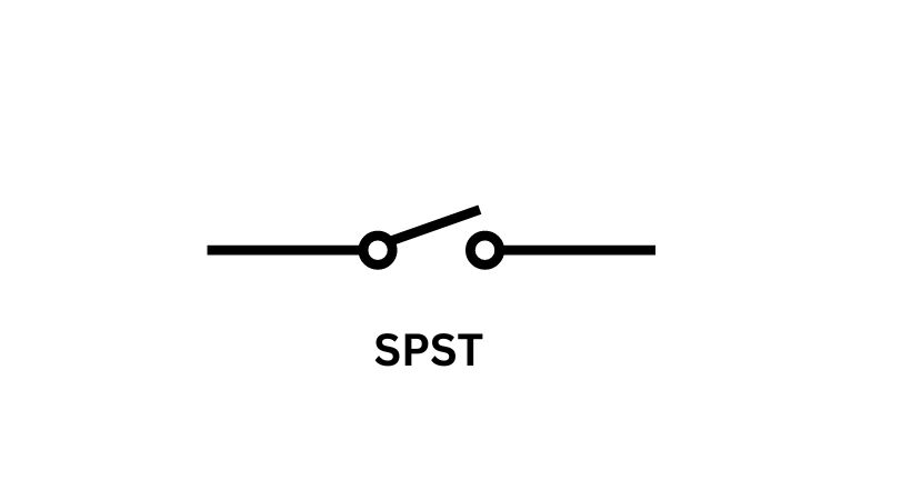
The single-pole/single-throw has one discontinue line with an actuator line. The actuator makes the switch on and off.
There are other types of switches also such as SPDT, DPST, and DPDT. Each one has its own circuit symbols.
7. Power sources
There are two types of power sources: DC power source and AC power source. In the circuit schematic, each one is represented differently.
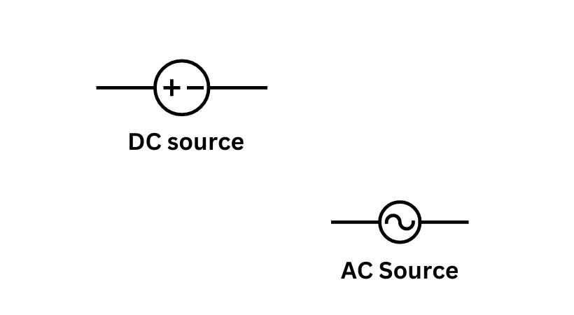
The DC source has positive and negative within the circle and the AC source has a wave shape in the circuit.
Batteries are also used as a power source. Regardless of whether they are rechargeable lithium-polymers or cylindrical, alkaline AA batteries, batteries typically resemble two uneven, parallel lines:

8. Voltage nodes and ground
In some schematics, there are special symbols used for voltage and ground.
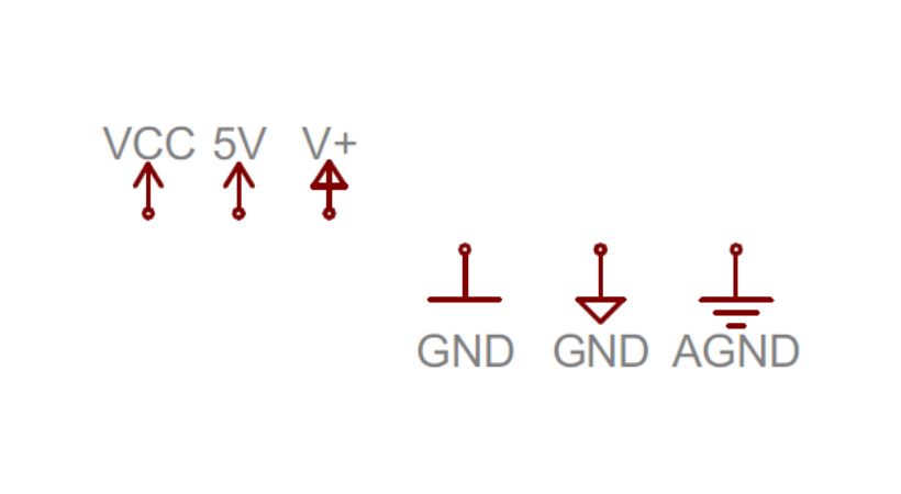
These are the symbols used for voltage and ground in circuit schematics.
9. Wires and connections in schematics
There is also a special representation for the wires and connection in the circuit schematics. The wire is represented by simple lines.
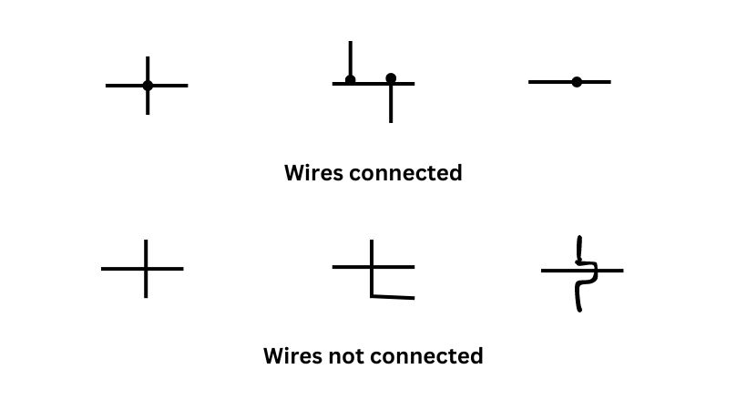
If the two wires are crossed and there is a small dot or node on it, it means they are connected. If no dot or node is available it means that wires are not connected they just pass over each other.
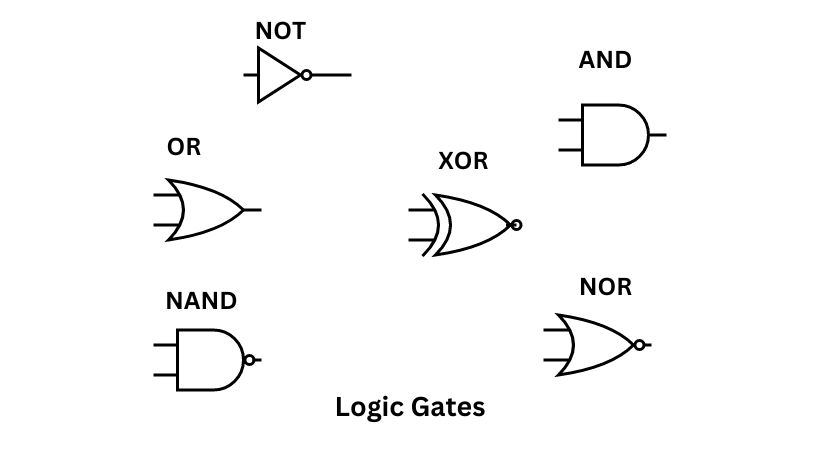
11. Logic gates
In digital electronics, the logic gates are used. The logic gates include NOT, OR, AND, XOR, NAND, and NOR.
Each of the gates has a specific symbol in circuit schematics. Here are the symbols of logic gates.
12. Operational amplifiers
Operational amplifiers are voltage amplifiers that typically have one output and one or more inputs. Another name for them is op-amps. An op-amp’s schematic symbol is as follows:

13. Integrated circuits
Integrated circuits (ICs) are fundamental components in modern electronic systems. It typically has a rectangular or square shape.
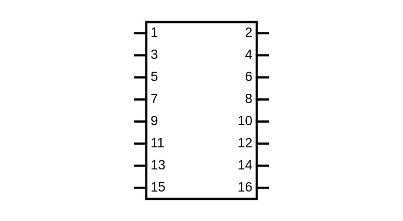
Integrated circuits have different pins. Each pin on an IC is labeled with a number and sometimes a function (e.g., Vcc for power, GND for ground, IN for input, OUT for output).
Interpret a circuit schematic
Let’s see how can you read a circuit diagram. Here are some key steps:
- The first step is to understand each component in the circuit schematic.
- Identify the connections and no connection, if there is a dot then there is a connection and no dot means no connection.
- The components in the circuit schematic are well-defined, which means all components have their values and labels. Like resistor is represented by “R” along with the value in Ohms.
- Understand the flow of current, starting from the positive of the battery, and see which components are connected and how are they connected.
- Determine whether the circuit is series, parallel, or aligned, as this will inform your understanding of its behavior.
These are the steps that will help you in reading a circuit diagram.
Now let’s a simple example:
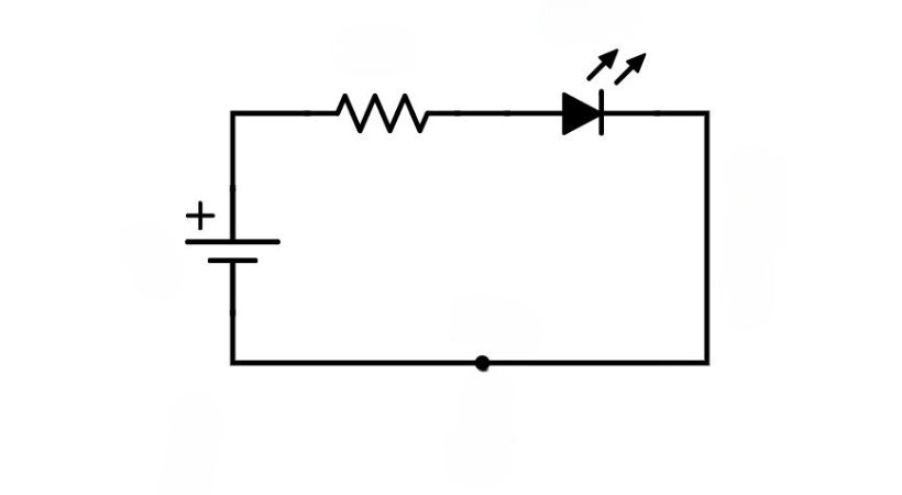
The above is a simple LED circuit with a battery, resistor, and LED.
- First, identify the components, the zig-zag line represents the resistor, the two on the triangle represent LED, and the two parallel lines represent a battery.
- Now read the circuit, the battery’s positive terminal connects to one end of the resistor.
- The other end of the resistor connects to the anode (positive side) of the LED.
- The cathode (negative side) of the LED connects back to the negative terminal of the battery.
This is how you can read a circuit and after that, you can build it also.
Conclusion
A circuit schematic is the graphical representation of the electrical and electronic circuits. It is also known as a circuit diagram.
They are indispensable tools in the field of electronics engineering. They allow us to troubleshoot, innovate, and understand the circuit behavior.
For circuit schematics, there are well-defined symbols that are used internationally. Like resistor has a zig-zag line and there are also different types of resistors each one has its symbol.
Components in the circuit should be identified by using the above diagrams. After that understand the current flow, start from the positive of the battery follow the path.
By understanding and utilizing circuit schematics, engineers and beginners can ensure their designs are both functional and reliable, paving the way for innovation and advancement in the field of electronics.
This is all about the circuit schematics, I hope next time you see any circuit you will have some idea which symbol represents which component.
Thank you and stay blessed…
Other useful posts: