DC current measurement on breadboard (2025)
Direct current (DC) is a fundamental aspect of electronic systems, it has given life to electronic circuits. Accurately measuring DC current is crucial for diagnosing issues.
A multimeter is capable of measuring various electrical parameters, including DC current. You have to rotate the dial to the DC current in milliamperes (mA). Remember that the multimeter measures the current only when connected in series with the circuit. After the mode selection, interpret the circuit and connect the multimeter to the point where you want to measure current, and the result will be shown on the multimeter display.
This article will delve into the details of DC current measurement on breadboard covering its principles, techniques, and practical considerations.
DC current
Direct current (DC) is a type of electrical current that flows consistently in one direction. In contrast to alternating current (AC), which periodically reverses direction, DC maintains a steady flow from positive to negative terminals.
DC finds numerous applications in various electronic devices, including batteries, solar cells, and many small electronics like smartphones, laptops, and household appliances.
It’s also used in certain industrial processes and transportation systems, such as electric vehicles and railway systems.
The measurement of DC current is crucial in various applications, including electronics, electrical, and power systems.
Let’s talk about how can you measure DC current using a multimeter.
Measurement on breadboard
Before going into the details of the measurement process let’s discuss what is a multimeter.
A multimeter, also known as a multitester or VOM (volt-ohm meter), is an indispensable tool for electrical testing and troubleshooting.
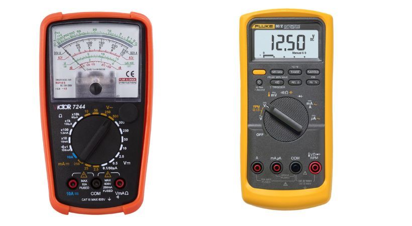
Based on display the multimeter is divided into two types: Analog and digital. The analog multimeter has a needle that points toward the measured readings.
The digital multimeter has an LCD that shows the measured reading in digit format.
If you are confused about which multimeter is good, check the article:

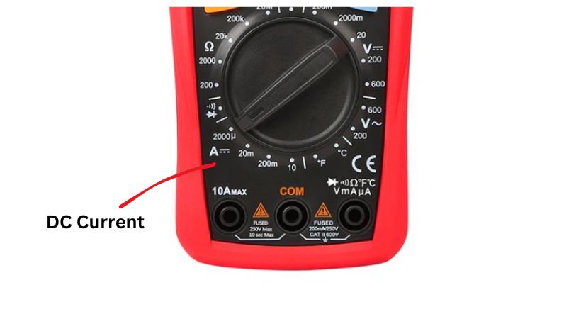
As the multimeter offers measurement of different parameters we have to select the mode for the measurement, so for this it has a selection dial that rotates and selects various measurement modes.
You must follow some steps for DC current measurement, let’s discuss what are these steps.
Step by step guide
Here’s a step-by-step guide for measuring DC current on breadboard using a multimeter:
1. Set the multimeter
The first step is to take out your multimeter and turn it on. Select the measurement mode.

In our case, the measurement mode or function is DC current mode. Turn the selection dial toward the DC current mode. This is typically denoted by the symbol “A” for amperes.
2. Select the range
If you are using a manual multimeter then you have to select the range for the DC current measurement. Start with the expected range and adjust as needed for better accuracy.
The auto-range multimeter selects the range automatically when connected to the circuit so this step can be skipped if you are using an auto-range multimeter.
3. Connect the probes
Now connect the testing probes of the multimeter. Insert the red probe into the “mA” or current jack of the multimeter. This is where the current will flow through the multimeter.
Connect the black probe to the common (COM) jack of the multimeter.
4. Current measurement
After connecting the testing probes, now is the time to measure the current in the circuit on the breadboard.
For the current measurement, we have to connect the multimeter in series with the circuit to allow current flow into the multimeter. The only way to connect the multimeter in series with the circuit is to interpret or break the circuit.
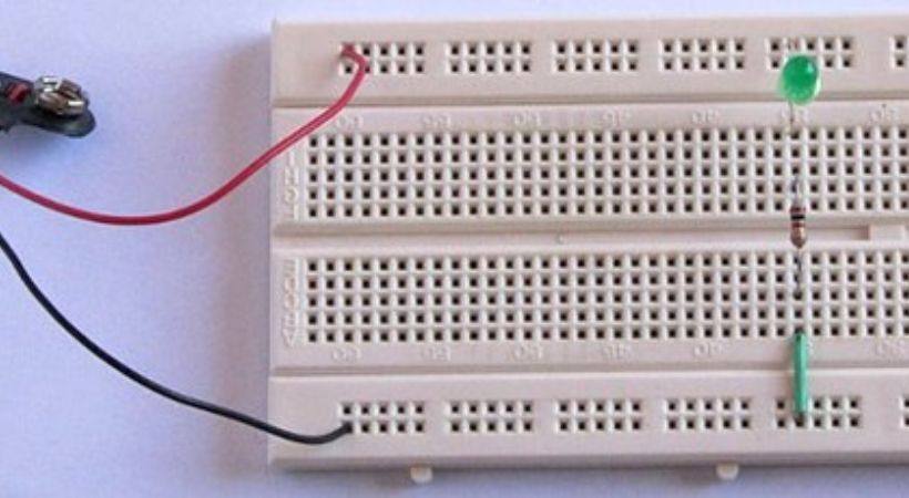
And make the multimeter component of the circuit to complete the path for the current flow. For example, we have the following circuit.

Now to break the circuit take the end of the resistor that is connected to the LED out and insert it in another column of the breadboard. The current flow is interrupted.
Take your multimeter and connect it in series with the circuit. Connect the red probe of the multimeter to the untouched resistor and the black probes to the unconnected LED. The LED will light up and the current will start flowing from the resistor to the multimeter to the LED.
This is how you have to connect the multimeter in series with the circuit to measure the DC current.
5. Take the measurement
Once the probes are securely connected, observe the multimeter display for the current reading.
If using a digital multimeter, the value will be directly displayed in amperes. For analog multimeters, the needle will indicate the current on the scale.
6. Interpret the measurement
Note down the measured current value. Ensure that you pay attention to the unit of measurement (usually amperes or milliamperes) and the polarity of the current flow.
You can repeat the process multiple times to be sure about the multimeter-measured readings.
If the multimeter has auto-ranging capability, it will automatically adjust the range for optimal accuracy. Otherwise, manually adjust the range as necessary to obtain a precise reading.
7. Disconnect the probes
After getting the measurement, disconnect the probes from the circuit carefully.
Turn off the multimeter and return the selection dial to the off position to save the battery life.
Safety Tips
Here are some safety tips that should be considered while measuring current in the circuit.
- Always use the appropriate range and function on the multimeter to prevent damage and ensure accurate measurements.
- Take precautions to avoid short circuits or overloading the multimeter, especially when measuring high currents.
- Use caution when working with live circuits, and wear appropriate personal protective equipment (PPE) as needed.
- Regularly calibrate the multimeter to maintain accuracy and reliability.
- Verify that the multimeter is rated for the expected current levels before making measurements to avoid damage or safety hazards.
By following the safety precautions you can measure the DC current accurately and safely.
Conclusion
The DC current measurement is a fundamental skill for anyone who is working with electrical and electronic circuits.
Various tools can be used to measure the DC current but the most convenient and versatile tool is the multimeter.
The use of a multimeter for DC current measurement is a straightforward process. First, you have to select the mode of the measurement by rotating the selection dial.
Range should be selected according to the expected current range. The multimeter is always connected in series with a circuit to measure current.
To connect in series, we have to break the circuit and connect the multimeter in such a way that it is considered a circuit component.
Now connect the probes of the multimeter, the red one to the component that breaks the circuit and the black one to the other end, in this way the circuit will be completed, and the current will start flowing.
After the connection, the multimeter will display the readings. Note the reading for further use and disconnect the probes.
So this is how we measure current on the breadboard using a multimeter, I hope this article will be useful.
Thank you and stay blessed…
Other useful posts:
