Diode measurement (Using multimeter, 2025)
Diodes are the components that allow the current to flow in one direction. Understanding how to measure diodes is crucial for troubleshooting circuits, testing components, and ensuring proper functionality.
A multimeter is a tool that is very crucial for diode measurement or testing. It has a specially designed function called diode mode which provides a small voltage to the diode and measures the voltage drop across the diode. If the multimeter doesn’t have diode test mode we can also use resistance to measure the resistance to test or measure the diode functionality and troubleshoot the circuit.
In this article, we’ll explore the basics of diode measurement using multimeter, a versatile tool commonly used by electronics enthusiasts, technicians, and professionals.
Understanding diode
Before discussing the diode measurement, it is essential to understand the diode.

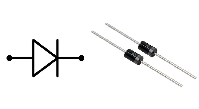
A diode is a fundamental electronic component with two terminals, known as the anode and the cathode. It allows current to flow in one direction only, effectively acting as a one-way valve for electrical current.
The diode is the polarized component means it has positive and negative terminals. The terminal of the diode can be identified. Most of the diode has a strip at one end which helps in finding the cathode terminal of the diode.
When the diode is forward biased it means when the anode is connected to the positive terminal of the battery and the cathode to the negative terminal of the battery, it conducts current easily, allowing electricity to flow through it.
Similarly, when the diode is reverse biased, the anode is connected to the battery’s negative, and the cathode to the positive terminal of the battery blocks the flow of current, offering a high resistance.
Symbols like “A” and “K” also be written on a diode to identify the anode and cathode respectively.
Diodes play critical roles in rectifying AC to DC, protecting circuits from reverse polarity, and regulating voltage levels.
The measurement of the diode is crucial as it tells us if the diode is good or bad. Let’s discuss how can we measure diodes using a multimeter.
Diode measurement using a multimeter
The multimeter measures the diode with a specially designed function called diode test mode, but some multimeters don’t have this function.
Don’t worry, we can also use voltage and resistance mode to test the diode. Let’s discuss these in detail.
1. Diode test mode
In this diode test mode, the multimeter applies the small voltage across the diode and measures the voltage drop across it.
To measure the diode using a multimeter with diode test mode, here are the steps you should follow:
Set the multimeter: Many digital multimeters have a specific diode test mode represented by a diode symbol (usually a triangle with a line at one end). If your multimeter has this mode, select it. Also insert the testing probes, the black one in the COM jack and the red one in the VΩ jack of the multimeter.
Turn off the power: If the diode is part of a circuit, ensure that the power to the circuit is turned off. Testing components, while they are powered, can damage the multimeter or the component being tested.
Identify the diode terminal: As we have discussed earlier, the diode has a positive and negative terminal called anode and cathode. The cathode is typically marked with a band on the diode body.
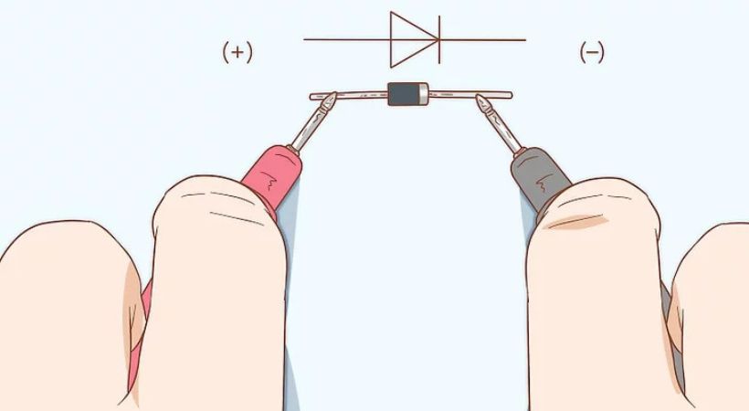
Connect the multimeter probes: In the diode test mode, connect the multimeter probes to the diode leads. The red probe should be connected to the anode (positive terminal) of the diode, and the black probe should be connected to the cathode (negative terminal).

You can also reverse the connection, and connect the red probe to the cathode and black to the anode.
Read the multimeter display: After the secure connection, the multimeter will display the results. The multimeter will typically display the forward voltage drop across the diode (in volts). A low forward voltage drop of around 0.6 to 0.7 volts for a silicon diode and 0.2 to 0.3 for a germanium diode, indicates a healthy diode.
For reverse connection, the multimeter will display “OL” indicating an open switch.
Interpret the results: If the multimeter indicates a low forward voltage drop in the forward direction and an open switch in the reverse direction, the diode is likely functioning correctly. If the results are different, the diode may be faulty and require replacement.
2. Resistance mode
If your multimeter does not have a diode testing mode you can resistance mode to check or measure the diode.
The following steps can be used to measure the diode.
- First, set the multimeter to the resistance mode and insert the testing probes in the recommended jacks.
- Make sure the power to the circuit is turned off to prevent damage to the multimeter and components.
- Identify the anode and cathode terminals of the diode.
- Now connect the probes, the red probe to the anode and the black to the cathode so this forward biased connection.
- In this case, a good diode will show resistance ranges from 1 kΩ and 10 MΩ, depending upon the type of diode.
- Now reverse the multimeter connection, and connect the red probe to the cathode and the black probe to the anode of the diode.
- Read the multimeter display again, it will display “OL” which means infinity resistance if the diode is good.
- If the diode doesn’t display the above results it means the diode is bad.
By following these steps you can test or measure the diode using a multimeter which doesn’t have diode test mode.
Importance of diode measurement
The diode measurement or testing is crucial for several reasons. Here in this section, we are highlighting the importance of diode measurement.
1. Circuit troubleshooting
Diodes are often used in various electronic circuits, and when a circuit malfunctions, diagnosing the issue often involves testing the diodes.
By measuring diodes, technicians can identify faulty components and determine whether they need to be replaced to restore circuit functionality.
2. Component testing
Before connecting any electronic component, it is recommended to check if it is functional or not. The diode is also an electronic component, it needs to be checked before connecting it to the circuit.
It is essential to verify diode characteristics, such as forward voltage drop and reverse leakage current. Testing diodes ensures that they meet specifications and perform as expected within the circuit.
3. Design verification
Engineers use diode measurement during the design phase of electronic systems to validate circuit performance and functionality.
By accurately characterizing diodes, engineers can optimize circuit designs, ensure compatibility with other components, and achieve desired system behavior.
4. Prevent damage
The diode is a polarized electronic component. It should be connected in the right way to operate properly and does not harm or damage other components.
The diode measurement allows us to identify its terminals and helps prevent such problems by confirming correct installation and functionality before applying power to the circuit.
Conclusion
A diode is a specialized component in electronics that allows the flow of current in one direction and blocks it in another direction.
A tool like a multimeter is used to measure or test a diode. The multimeter, which is also called multifunction has a dedicated function to measure the diode.
The two functions called diode test mode and resistance mode are used to measure the diode. Most of the recent multimeter has diode test mode.
All you have to do is set the multimeter to diode test mode and connect the probes of the multimeter across the diode anode and cathode. The multimeter will display the results.
If your multimeter doesn’t have a diode test mode you can use the resistance mode of the multimeter. Set the multimeter to resistance mode and check the forward and reverse resistance of the diode.
Remember to exercise caution when handling electronic components and always refer to the multimeter’s user manual for specific instructions.
This was all about the diode measurement, I hope it will be helpful.
Thank you…
Other useful posts:
