
The short circuit causes high current to flow, bypassing the intended path of the circuit and leading to malfunction, and damage to the components.
It is essential to find short circuits on the breadboard to avoid damage to the components and circuit. The visual inspection and use of a multimeter with continuity or resistance mode are effective methods to find shorts on the breadboard.
In this article, we’ll discuss how to find short circuit on breadboard.
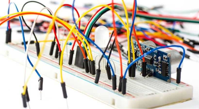
Short circuit on breadboard
Sometimes, when working on building a circuit on the breadboard, the two wires or components’ pins get connected unintentionally, causing the current to flow in this unintended connection, whichn leads to the burning of components.
Let’s discuss how you can find short circuit on the breadboard.
1. Visual inspection
The first method is visual inspection, carefully inspecting the connections of the circuit on the breadboard for any obvious miswiring. Ensure that components and wires are not connected to the wrong rows or columns.
Remember, the loose wire can cause short circuits easily, so it is essential to make sure that all wires are securely connected.
Components like resistors, capacitors, and ICs are placed in the right place, and check if any components are touching each other or not.
Visual inspection will give you a little bit of an idea about shorts on the breadboard, so thoroughly observe the circuit on the breadboard.
2. Use of a multimeter
The multimeter is a device used for electrical parameter measurements. It also helps in finding short circuits on the breadboard.
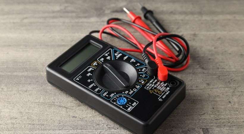
Two modes, continuity and resistance modes, are used to identify short circuits on the breadboard.
Continuity mode
Follow the following steps to find shorts using the continuity mode of the multimeter.
- Take out continuity.
- Connect the probes and insert the black probe into the common (COM) jack and the red into the VΩ jack.
- Turn the multimeter dial to the continuity mode.
- Test the multimeter by touching the probes together. if a beep sound is heard, it means the multimeter is working properly.
- Now, identify the suspected point where you think an unintended connection is created.
- Take the multimeter probes and touch one probe to each point on the breadboard.
- If the multimeter beeps, it indicates there is continuity (i.e., a low-resistance path) between the two points, suggesting a short circuit.
- If there is no beep, there is no direct connection between those points.
The following are the steps to find short circuits on the breadboard using the continuity mode.
Resistance mode
If your multimeter doesn’t have a continuity mode, the resistance mode can also be used. In this method, the multimeter measures the resistance between two points.
Let’s discuss how you can use the resistance mode of the multimeter to find short circuits.
- Set the multimeter to resistance mode.
- Connect the probes.
- Touch the probes together. If the multimeter shows a reading close to zero, it indicates the multimeter is correct.
- Decide which points in the circuit you suspect might be shorted.
- Place the multimeter probes on the points you want to test.
- Observe the resistance readings.
- A very low resistance reading indicates a short circuit.
- A high resistance or an open circuit (infinite resistance) indicates no direct connection between the two points.
Using the resistance mode of a multimeter is a reliable way to find shorts on a breadboard, helping to ensure your circuit operates correctly and safely.
This is how a multimeter is used to check the circuit for short circuits.
Tips to avoid short circuits
Here are some tips to avoid short circuits on a breadboard:
- Organize your wires and avoid overlapping wires.
- Use specific color wires, for example, red for power and black for ground, to avoid confusion.
- Always double-check your connections against the circuit diagram before powering up.
- Keep the power and ground rail separated.
- Carefully insert the components into the correct rows and columns.
- Inspect the breadboard for loose wires or components.
- Check the continuity before applying power.
- Ensure that all components are securely placed in the breadboard holes.
Conclusion
Shorts are unindented connections that cause low-resistance paths for current to flow from them. This can cause fire and damage the components.
It can take some time to find shorts on a breadboard, but with the correct tools and a methodical approach, it can be done with ease.
First, you can visually analyze the circuit on the breadboard to find short circuits. This is a simple method, and by checking different connections, shorts can be identified.
The next method is the use of a multimeter. The multimeter is one of the most used tools in electronics to measure different parameters. The resistance and continuity modes are utilized.
In continuity mode, the multimeter beeped to indicate short circuits. The multimeter shows a low resistance value in resistance mode to identify short circuits.
With these methods, you can ensure your circuit functions correctly and avoid potential damage or safety hazards.
This was all about finding shorts on the breadboard, I hope you enjoyed this article.
Happy prototyping!
If you want to learn more about troubleshooting circuits on a breadboard, check the article “ How to find an open circuit on breadboard”.