Understanding multimeter symbols (For measurement, 2025)
Multimeter have different symbols for each parameter so understanding the symbols displayed on a multimeter is crucial for accurate measurement and troubleshooting.
The multimeter has a “V” symbol to represent voltage, “A” to show current, (Ω) for resistance, the continuity symbol typically resembles a sound wave or a diode symbol, capacitance is represented by “F” for farads and frequency “Hz” for hertz. These are the symbols of the multimeter that help in selecting different measurement modes.
In this article, we’ll delve into the meaning behind common multimeter symbols and how they relate to electrical measurements.
Multimeter symbols
The multimeter is a beginner-friendly device that helps them test the components and measure the different electrical parameters to understand the electronic circuit effectively.

It is also helpful in designing various circuits. There are two main types of multimeters: Analog and Digital.
The main difference between these two is the way they display the measurements. We also have a detailed article on it, if you want to learn more about here is the link…
As you can see in the above picture the multimeter has different symbols to show by rotating the selection dial which electrical parameter a multimeter can measure.
As a beginner, these symbols must be confusing for you but don’t worry we can help you to understand and learn all these symbols to design your circuit.
So let’s go into the details without boring you.
1. Input jacks
A typical multimeter features several input jacks, each designated for specific measurement functions. The most common input jacks include those for voltage (V), current (A), and common (COM) connections.
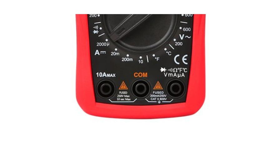
As you can see in the above picture, three input jacks are designed to measure specific measurements.
10AMAX: The red probes will be inserted into this jack if want to measure current in amperes and the 10 means you can measure it up to 10Ampere.
COM: The common input jack serves as the reference point for voltage and current measurements. It’s where black test lead is typically connected when performing measurements.
VmAµA: If you want to measure the voltage, resistance, temperature, capacitance, diode, continuity testing, and current in mili and microampere you have to connect the red lead to this jack.
The input jacks of the multimeter can be different for different multimeters. Always refer to the multimeter’s user manual and follow safety guidelines when using input jacks for measurements.
2. Voltage
Voltage represents the electrical potential difference between two points in a circuit. It indicates the force that drives electric current through a conductor.
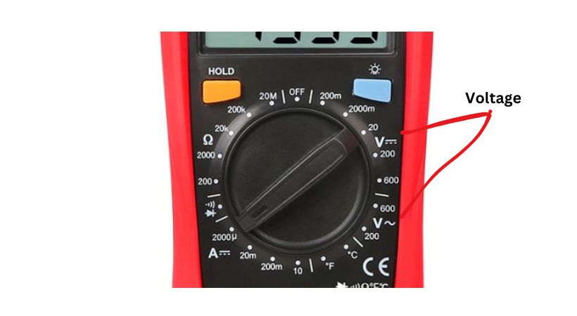
In the auto-range multimeter, the multimeter picks the range of voltage but in manual, you have to select the range.
The symbols for voltage on the multimeter are as follows:
- “V” represents voltage in general.
- “V~” denotes alternating current (AC) voltage.
- “V⎓” represents direct current (DC) voltage.
This function is used to measure the voltage across components or points in a circuit.
3. Current
Current symbolizes the flow of electric charge in a circuit. It indicates the rate at which charge moves through a conductor. It is measured in ampere (A).
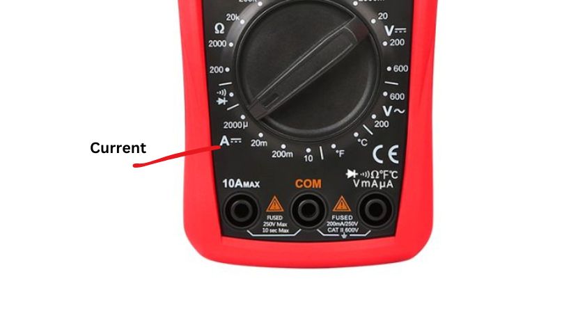
Keep in mind that the manual range multimeter has numbers also written along with symbols so be confused that is just for the expected range in which you want the multimeter to measure the current.
The symbols are used for the current to identify current measure functions.
- “A” represents current in general.
- “A~” denotes alternating current (AC) current.
- “A⎓” represents direct current (DC) current.
When you rotate the selection dial of the multimeter toward A, it means now multimeter will measure current. Make sure you connect the probe to the right jack for measuring current.
4. Resistance
Resistance represents the opposition to the flow of electric current in a circuit. It indicates how much a component or material resists the passage of current.
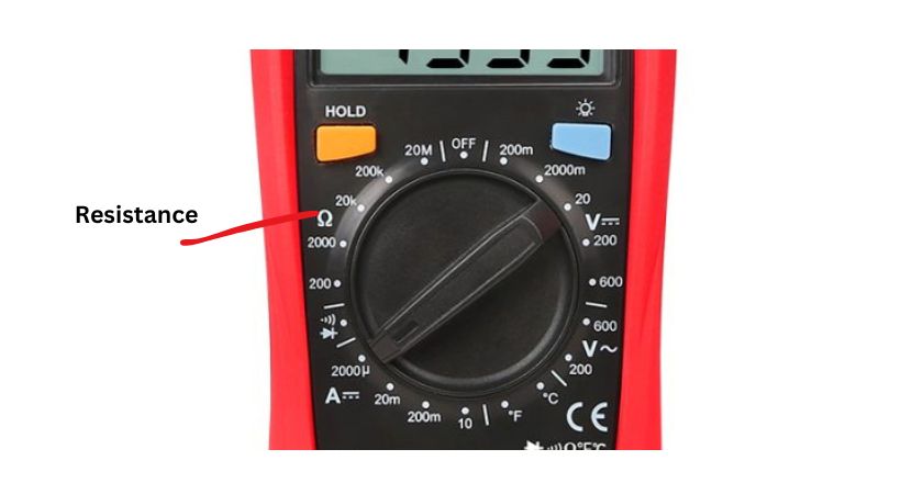
The resistance is measured in Ohms (Ω) so it is also used to show the resistance measurement function of the multimeter.
In the manual multimeter, the range of resistance is given you have to estimate the resistance range and rotate the selection dial.
In the auto range, you don’t have to worry about the range, the multimeter automatically picks the range.
The multimeter has the following symbol to show resistance.
Symbol: omega (Ω).
This function helps to measure the resistance of resistors, conductors, and other components in a circuit.
5. Capacitance
Capacitance measures a component’s ability to store electrical charge. It indicates how much charge a capacitor can store per unit voltage. It is measured in Farads (F).
The symbol for capacitance is,
Symbol: Represented by “F” for farads or by two parallel lines.
This function is used to measure the capacitance of capacitors and evaluate their performance in circuits.
6. Continuity
Continuity indicates whether there is a complete path for current flow between two points in a circuit.
Continuity testing is immensely helpful for identifying faults such as broken wires, loose connections, or faulty components in a circuit.
For instance, if a wire is broken or a connection is loose, there will be no continuity, and the multimeter will not beep.
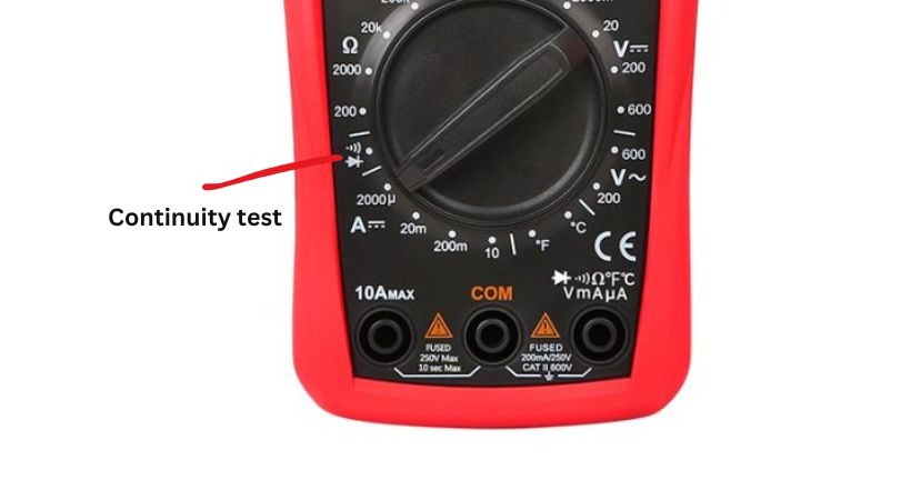
Symbol: The symbol used for continuity is a sound wave or a diode symbol.
When you set the dial on the continuity mode, now you’re all set to test the continuity of the circuit and identify the faulty components.
7. Frequency
The Frequency measures the number of cycles per second in an alternating current (AC) signal. It indicates how fast an AC signal oscillates. The unit of frequency is Hertz (Hz).
Symbol: Represented by “Hz” for hertz.
The function is used to measure the frequency of AC signals in electronic circuits.
8. Temperature
Some multimeters feature temperature measurement capabilities using a temperature probe. The temperature is measured in Degrees Celsius (°C) or Degrees Fahrenheit (°F).
Symbols for Celsius (°C) and Fahrenheit (°F) are used accordingly.
Symbols: Represented by “°C” for Celsius and “°F” for Fahrenheit.
This multimeter feature is used to measure the temperature of surrounding factors, circuits, and electronic components.
These are the symbols used in multimeters to show various electrical parameters measurements.
By understanding these symbols you can easily and efficiently use a multimeter for your electronic and DIY projects.
Conclusion
Understanding multimeter symbols is essential for anyone working with electrical circuits.
By familiarizing themselves with these symbols and their meanings, engineers and technicians can perform accurate measurements, diagnose faults, and troubleshoot circuits effectively.
A multimeter can measure:
- Voltage
- Current
- Resistance
- Capacitance
- Frequency
- Temperature
A multimeter can also test the components by using the continuity testing feature. Each measurement feature of the multimeter has its specific symbol.
For voltage we have “V”, for current “A”, for resistance we have omega, for capacitance we have two parallel lines and so on.
That’s it about the multimeter symbols, I hope the information provided in this article, readers can confidently navigate the world of multimeters.
Thank you and stay blessed…
Other useful posts:
