
Open vs closed circuit in electronics with examples (2025)
Circuits are divided into two types, Open and Closed, based on their ON and OFF states.
An open circuit is like an interrupted path for electricity. The electrical path has a break, and the current cannot flow. On the other hand, the closed circuit is a complete, uninterrupted path for electricity to flow. A closed circuit allows current to move from the power source through the various components and back to the source.
In this article, we’ll discuss the open and closed circuits in detail for beginners to understand them well.
Open and closed circuit
Before going into the details of circuit types on the base of state, let’s see what is a circuit.
An electronic circuit is the building block of every electronic device, ranging from simple devices like flashlights to complex systems like computers and smartphones.

The electronic circuit is a closed loop of conductive material through which electric current can flow.
The different electronic components are arranged in a specific order in the network to perform specific tasks.
Some key components of an electronic circuit are as follows,
- Power source
- Resistors
- Capacitors
- Inductors
- Transistors
- Diodes
- Integrated circuits
- Connecting wires
- Switches
For more detailed learning of circuits, I suggest you see our article:
Let’s talk about the types of circuits in detail.
1. Open circuit
An open circuit occurs when there is discontinuity or interruption in the continuity of electricity flow. In other words, there is a gap in the circuit, which prevents the flow of current.
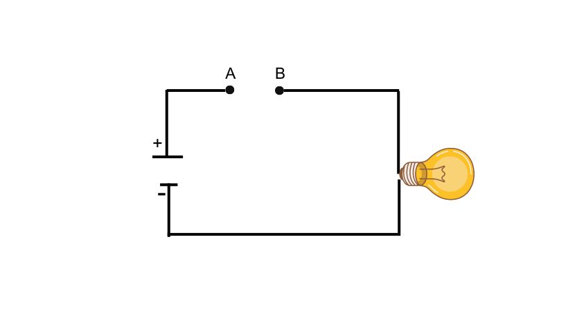
If you see the circuit, you can see there is a breakage in the circuit connection so no current is flowing and the light bulb is off.
It is the same as there is a gap in a road and it interrupts the traffic flow. In an open circuit, no current flows from the source to load due to the break in the circuit. Therefore, it represents the off state.
Any malfunctioning component in the circuit or an off switch or breakage in connective wire could be the cause of the open circuit.
The interesting facts about open circuits are:
- There can be any voltage value across the points i.e. for example in the above picture points A and B have any value voltage.
- In an open circuit, the resistance between the open points is considered infinite because no path is available for the current.
- No current flows through the open circuit whatsoever.
In very simple words for beginners, when we cut a connection between any two components we make an open connection there.
Example of open circuit
Let’s consider a simple example to understand the open circuit.
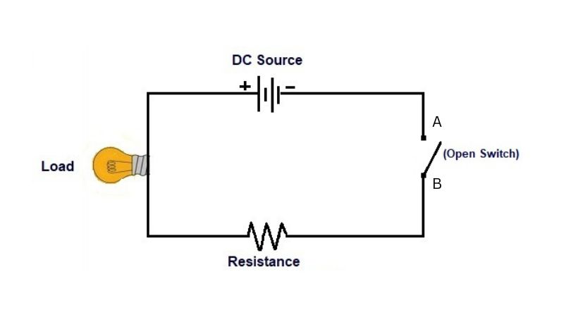
In the above circuit, you can see there is an open switch which means there is a discontinuity in the circuit so it will prevent the flow of current, and the load bulb will remain off.
The resistance of an open circuit is infinite because of zero current flow in a circuit. From Ohm’s law, we know that.
V=IR
And
R=V/I
As the current in an open circuit is zero so
R=V/0
R=∞
Discontinuity and openness in the circuit prevent the current from flowing through to it because it has infinite resistance.
Identifying open circuit
A multimeter is a tool that is used to calculate various electrical parameters like voltage, current, resistance, and many more.
Follow the following steps:
- Turn on the multimeter.
- Connect the probes to the multimeter.
- Set the meter to the continuity mode.
- To test the multimeter functionality, connect the probes together if you hear a beep sound it means the multimeter is working fine.
- Turn off the power to the circuit.
- Now test the circuit, place the two probes at different points on the circuit you want to test.
- If you hear no beep sound it means the circuit at these points is open.
This is how you can test your circuit for open or discontinuity. The resistance mode of the multimeter is also used to test open circuits but the difference is it will show infinite or high resistance values on the display.
2. Closed circuit
A closed circuit is a complete, uninterrupted path for an electric current to flow. A closed circuit means there is no gap or break in the circuit so a constant current is flowing.
It is like a closed-loop road system where vehicles can continuously move from one point to another. So the circuit that has a constant flow of electric current from source to load is called a closed circuit.

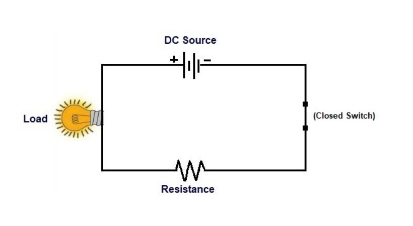
As you can see in the above circuit, the path for the current flow is complete so the current will flow from the source (battery) to the load (light bulb).
The resistance of closed circuits is less than the open circuit and it defines the load connected to it. The closed circuit represents the ON state.
The basic thing that should be known about closed circuits is the following.
- The applied voltage in closed circuits is distributed between the connected loads.
- The current flows in the closed circuit.
For circuits to operate properly the path between the supply voltage and the load should be closed.
Example of Closed Circuit
To understand closed circuits more let’s talk about an example.
The main components of a closed circuit are
- Power source
- Conducting wires
- Electric load
When these components join together form a closed loop and provide a path for the continuous flow of current.
In the above example, you can see the switch is closed and the path is complete. The complete path allows the current to flow and glow up the load blub.
This is the same when you press the button in your home and the electric fan or light turns on.
Identifying closed circuit
For closed-circuit identification, we also used a multimeter. Follow the step-by-step process provided here.
- Turn on the multimeter and connect the testing probes.
- Set the multimeter to continuity mode.
- Disconnect the power source to the circuit.
- Place one probe at each end of the section of the circuit you want to test.
- If the circuit is closed, the multimeter will emit a beep, indicating a complete path for current flow.
A continuity test using a multimeter is an easy method that quickly identifies if a circuit is open or closed.
Open Vs. closed circuit
The two states of the electronic circuit are represented by open and closed circuits. Some significant differences between both are the following.
| Open circuit | Closed circuit |
| Open circuit is an incomplete path and it prevents the flow of current from source to load. | A closed circuit is a complete path and it allows current to flow from source to load. |
| It represents the OFF state of the circuit. | It represents the ON state of the circuit. |
| The open circuit is represented by “( )” in an electric circuit. | The closed circuit is represented by “(.)” in an electric circuit. |
| The current does not flow in an open circuit. | Current flow in a closed circuit. |
| The whole supply voltage appears across the circuit’s open terminals when it is an open circuit. | In a closed circuit, the supply voltage is distributed across the loads depending on the load parameters. |
| In an open circuit, the resistance is infinite ideally but practically very high. | The resistance of the closed circuit is less than the open circuit and it depends upon the circuit elements and resistance of wires. |
| An open circuit has a discontinuous path. | A closed circuit has a continuous path. |
| A lamp circuit with the switch in the off state is a typical illustration of an open circuit. | A lamp circuit with the switch in the ON state is an example of a closed circuit. |
Conclusion
In the world of electronics, the concepts of open and closed circuits are foundational. Based on ON and OFF states the electronic circuit has these two types.
The open circuit is incomplete or discontinuity in the path which stops the flow of electric current from source to load. It represents the OFF state of the circuit. The resistance of this circuit is very high.
On the other hand, a closed circuit is a complete path that allows the flow of electric current from the source to the load. The ON state is represented by a closed circuit and its resistance is dependent upon the circuit elements and resistance of a wire.
When the bulb in the circuit is off it means the circuit is open or the switch is off and no current is flowing. But if the same bulb is on means the circuit is closed or the switch is ON and the current is flowing.
So by visualizing circuits as paths with the potential for interruption or continuity, you gain insight into the inner workings of electronic devices.
This was all about open and closed circuits, I hope this easy explanation will help you to understand these concepts of circuits.
Thank you…
Excellent