
The correct placement of the IC on the breadboard is the step that requires special attention, wrong placement can lead to damage to the IC.
To properly place an IC on a breadboard, first understand that the breadboard has a central gap dividing two sets of connection rows. Position the IC so it straddles this gap, with half of its pins on each side. Avoid placing the IC in the main breadboard area to prevent short circuits. Before connecting, ensure you identify the IC pin configuration correctly.
In this article, I will discuss each step of the IC placement on the breadboard in detail along with common mistakes that should be avoided.
Placing IC on breadboard
Integrated circuits (IC) are mini electronic devices that consist of transistors, resistors, capacitors, and other electronic components fabricated on them.
These tiny chips can perform a wide variety of functions, from simple logic operations to complex signal-processing tasks.
ICs are fundamental to modern electronics, enabling the creation of compact, efficient, and powerful devices such as computers, smartphones, and various digital and analog applications.
Correct and efficient Putting an IC breadboard is crucial for the overall performance of the circuit and the IC. If the IC is placed incorrectly, it will not perform as intended.
Let’s see how I can put the IC on the breadboard correctly. Here’s a step-by-step guide to help you to place the IC properly.
1. Understand the breadboard
First, understand the breadboard layout. It has two portions: power railing and main components connection area.
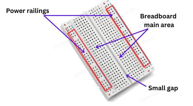
The upper and lower parts of the breadboard are power railings, the “+” and “-” signs indicate that the power source will be connected here. The power railing holes are connected horizontally.
In the middle of the power railing, there is the main area of the breadboard where the circuit will be built. The breadboard main is divided into two parts and there is a small gap that disconnects each part from the other. The holes in this area are connected vertically.
For IC placement on the breadboard keep in mind this small gap between two parts of the breadboard’s main area.
2. IC pin configuration
After understanding the breadboard now select the IC you need. Different ICs have various pins.
The pin configuration of the IC is essential for its correct placement. Place the IC so that the notch or dot is at the top, so the left side of the IC indicates the position of pin 1. The 555 IC has 8 pins.
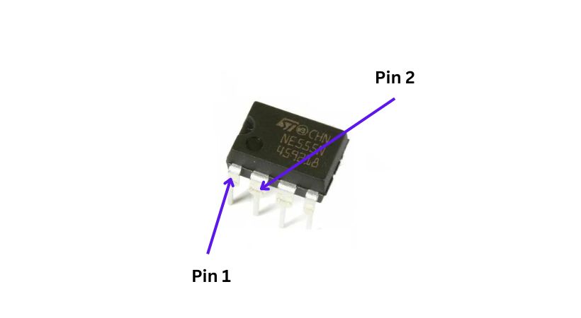
For 555 IC, from pin 1 count down to pin 4, and then from the bottom of the right side is pin 5 to pin 8. Refer to the datasheet of the IC to understand each function of the pin.
3. Insert the IC on the breadboard
As we discussed earlier the breadboard has a small gap that divides the two set rows.
So insert the IC in this small gap in such a way half pins are inserted in one set of rows and the other half in another set of row. Place the IC, so it notch and dot is at the top.
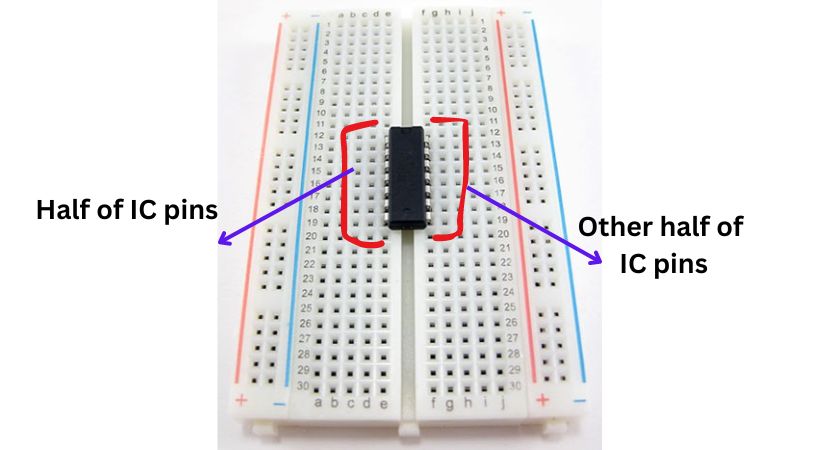
Gently press the IC into the breadboard. Ensure that all pins go into their respective holes and the IC sits flat. Be careful not to bend the pins.
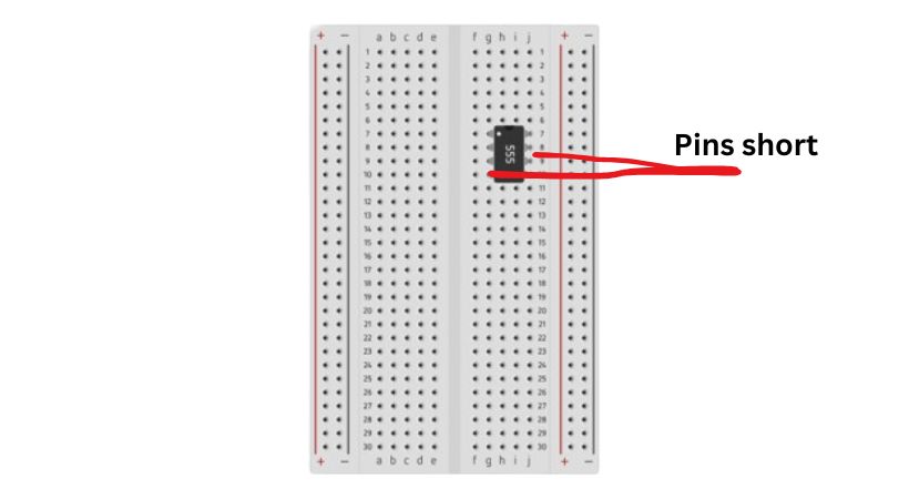
The IC can be connected into the two rows of the main area of the breadboard as the rows are connected vertically, it will short the pins of the IC.
4. Connection of the IC
Connect the IC in the circuit. Apply the power source and GND to the IC pins which are designed for the Vcc and GND.
Use jumper wires to connect other components (resistors, capacitors, LEDs, etc.) to the appropriate pins of the IC as per your circuit design.
Ensure that there are no short circuits and that all connections are secure. Verify that power is reaching the IC.
For proper and correct IC placement on the breadboard, following these steps will help minimize damage to the IC.
Common mistakes to avoid
When putting IC on the breadboard, some mistakes can be made which can lead to the IC damage.
Here are some common that should be avoided for correct placement of IC.
1. Putting IC in an incorrect place
The IC has pins on both sides so it should be connected in such a way that the pins don’t connect.
If the breadboard is placed into the main area of the breadboard it will short the pins leg. As the breadboard main area holes are connected vertically.
Placing IC with the wrong orientation is also a mistake that can be made. Always look for the notch or dot on the IC, which indicates pin 1, and orient the IC correctly on the breadboard.
Understand the breadboard and always place the IC in the correct place.
2. Misalignment pins
Pins not aligned with the holes in the breadboard, leading to bent or unconnected pins.
Carefully align the IC with the rows on the breadboard before pressing it down. Ensure that each pin goes into the correct hole.
3. Incorrect pin connections
As I had said earlier IC has various pins for different functions so understanding its functions is important for correct electrical connections.
Connecting power and ground to the wrong pins or miswiring other connections can lead to component damage or affect the circuit’s performance.
Double-check the IC’s datasheet for the correct pinout and verify connections before powering the circuit.
4. Loose connections
Not inserting an IC on the breadboard properly and connecting using jumper wires is not made correctly is the mistake that can happen. This will lead to intermittent connections.
Ensure all components and wires are securely inserted into the breadboard holes by applying little force.
When working with ICs on a breadboard, you can ensure a more reliable and functional setup by avoiding these mistakes and following these guidelines.
Conclusion
IC or integrated circuit has been an integral part of modern electronics, it has reduced the size of many devices.
As an electronics student, you will come across different projects where you will work with IC, so correct and proper placement of the IC on the breadboard becomes crucial.
Follow the following steps for IC placement:
- Understand the breadboard first
- Identify the pin configuration of the IC and its function
- Place the IC between the two sets of rows, so that half of the pins are on one side and the other half on the other side.
- Make the necessary connection to make the IC functional
Remember that mistakes can be made and consider it as the process of learning.
Avoid mistakes like placing the IC in the main area of the breadboard, not aligning the pins of the IC with holes, making incorrect pin connections, and not properly inserting the IC pin in the holes.
This is all about the IC placement on the breadboard, I hope it will be helpful.
Thank you and have a great life…
Other useful posts: