Sometimes we need to measure the resistance of the resistor on the breadboard for successful circuit design and troubleshooting.
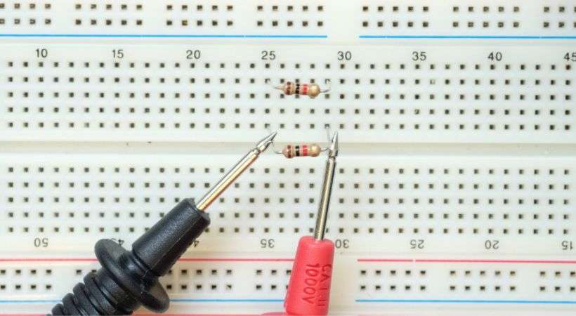
All you need is to select the right mode and turn off the power to the circuit, if you are using a manual multimeter so adjust the range. After that place the leads of the multimeter probes on each side of the resistor on the breadboard. Remember that the resistor has no polarity so it doesn’t matter which probes are connected to which side of the resistor.
In this article, we’ll discuss in detail how you will set up a multimeter for resistance measurement on the breadboard.
Resistance measurement on breadboard
The resistor is the electronic component and the resistance is a fundamental property of the resistor that impedes the flow of electric current.
It is measured in ohms (Ω) and is influenced by factors such as the material, length, and cross-sectional area of a conductor.
Resistors, the most common passive components used to introduce resistance into circuits, come in various types including fixed resistors and variable resistors.
Before going into detail about the resistance measurement of the resistor, let’s talk about what is the breadboard.
What is a breadboard?
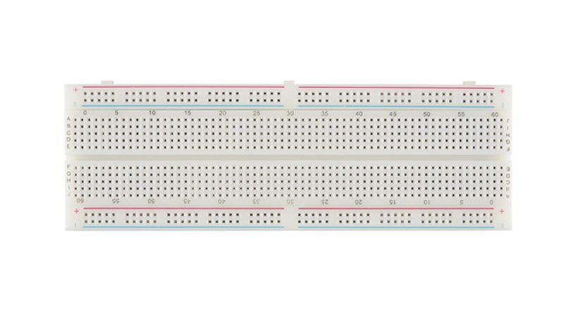
A breadboard is a fundamental tool used in electronics prototyping, providing a convenient platform for assembling and testing electronic circuits without the need for soldering.

It consists of a rectangular board with a grid of holes arranged in rows and columns.
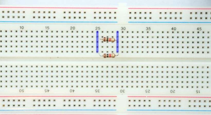
Beneath the surface of the board, metal strips connect the holes in a predefined pattern, allowing for electrical connections to be made easily.
These metal strips are typically arranged in two sets: the power rails along the edges of the board, labeled as positive (+) and negative (-).
Components, such as resistors, capacitors, integrated circuits, and jumper wires, can be inserted into the holes on the breadboard, with their leads making contact with the metal strips below.
The breadboard is an essential tool for the beginner to test and do iteration in their project.
We can measure different electrical parameters of the components when they are already connected to the circuit using various tools.
In the next section, the resistance measurement of the resistor on the breadboard will be discussed.
Step-by-step guide for resistance measurement
The multimeter is the tool or device used to measure the resistance on a breadboard. It has different functions such as voltage, current, and capacitance measurement.
It is also possible to test the resistor’s resistance without connecting it to the breadboard, but occasionally we need a safe location to hold the resistor so that the multimeter probes can be connected to it more effectively.
This is one case, it also happens the resistor is sometimes connected to the complicated circuit and if we remove it from the circuit connecting it would be a little challenging.
Here’s a step-by-step guide for measuring resistor values on a breadboard using a multimeter:
1. Set up your workspace
Place your multimeter and breadboard on an even surface. Maintain a clean workspace and sufficient lighting to enable precise measurements.
2. Prepare the breadboard
Insert the resistor you want to measure into the breadboard. Place each lead of the resistor into separate rows on the breadboard.

Ensure that the leads make good contact with the metal strips inside the breadboard.
3. Set the multimeter
Turn on your multimeter and connect the probes, black to the COM and red to the terminal that can have ohms symbols.
After that set the multimeter to the resistance (ohms) measurement mode.
If your multimeter has manual ranging, select an appropriate range based on the expected resistance value of the resistor. If it’s auto-ranging, this step may not be necessary.
4. Test the multimeter
You can also test your multimeter if it is good or bad. The two tests open and short circuit can be performed to test the accuracy of the meter.
In an open circuit test, the leads of the probes are kept untouched, and if the multimeter shows “OL” or “1” on the display the multimeter is good.
For short circuits, if the multimeter displays zero resistance after touching the leads of probes with each other, it also indicates that the multimeter is accurate.
If the multimeter doesn’t pass these two tests you need to replace the multimeter or check for any short or open connection in the multimeter.
5. Connect the probes
When the multimeter passes the above test, now it is time to measure the resistance of the resistor.
Take the multimeter probes and connect them to the leads of the resistor on the breadboard. Ensure that each probe makes good contact with the metal of the resistor lead and that there are no loose connections.

You don’t have to worry about the connection of probes as the resistor is the nonpolarized component so whatever you connect the probes it will provide you with the same results.
6. Read the measurement
Observe the reading displayed on the multimeter. This reading indicates the resistance value of the resistor being measured.
You can also note this value for reference.
7. Repeat the process
You can repeat this process. So If you have multiple resistors to measure, repeat steps 3-7 for each resistor individually.
Ensure that you reset the multimeter between measurements and that the breadboard connections remain stable.
8. Verify the results
You can also verify the measured result by comparing it with the color code reading of the resistors.
Remember that sometimes the measurement value does not exactly match the value that we get from the color code. This is because of the tolerance value, the value may deviate from the original one.
The resistance measurement is a very straightforward process so by following these steps you can effectively and accurately measure the resistance of the resistor on the breadboard.
Conclusion
Measuring the resistance of the resistor on the breadboard is essential.
Sometimes the resistor is connected to a complex circuit so you have to measure its resistance without disconnecting it.
It is also essential for successful circuit design and troubleshooting in electronics.
By understanding fundamental concepts, and employing proper techniques, electronic engineers can ensure an accurate measure of the resistance of the resistor with confidence.
The multimeter is used for the measurement, so make sure the multimeter you are intended to use is in good shape and accurate.
You have to set the multimeter on Ohm mode and by connecting the leads of the probes to the resistor, the multimeter can measure the resistance.
These were the simple steps that would help you in resistance measurement on breadboard, I hope this article will be helpful.
Thank you…
**We learned how to measure a resistor on a breadboard. Let’s continue our learning with a fun activity, i.e., to verify series and parallel resistance formulas using a multimeter.
