
In parallel circuits, there is more than one for the current to flow while in series circuits, there is a single path for the current flow.
The circuits in which components are connected in series are called series circuits. In a series circuit, the current flowing in each component is the same but the voltage is different. It is easy to design and easy to understand but susceptible to total circuit failure if one component fails.
In the article, we’ll explore what series circuits are, and how they work, and dive into examples to calculate their current, voltage, and equivalent resistance.
Series circuits
When learning electronic circuits, it’s essential to learn different combinations of circuits. One of the fundamental circuit configurations is the series circuit.
Let’s discuss the series circuits and how they work. The series circuit is defined as,
A series circuit is an electronic circuit in which electronic components are connected end-to-end in a single path, so the same current flows through each component.
The components are connected in line and there is only one path for the current to flow. The whole current flows through each component.
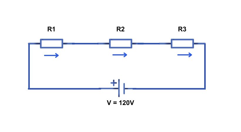
You can see in the above circuit, that the components which are resistors are connected in line and all the current from the battery is flowing in each resistor.
The series circuit is simple to design and very easy to understand as it has straightforward connections.
There are also some limitations of a series circuit such as if one component fails the entire circuit will stop working.
Characteristics
In a series circuit, components are connected in a single pathway so that the current has only one route to follow. This arrangement creates a sequential flow of electricity through each component.
Here are some characteristics of series circuits.
1. Current flow
In a series circuit the current flows in sequential form. There is no branching or division of the current; it passes through one component after another along the same path.
The current is the same throughout the circuit and the same current is flowing in each component. So if there are ‘n’ number of components in the circuit the current is
I_T = I_1 = I_2 =……………..= I_n
Where I_T is the total current flowing in the circuit.
2. Voltage distribution
The voltage in the series circuit is different across each component. The total voltage provided by the power source is distributed across all the components in the circuit. Each component utilizes a portion of the total voltage.
As the current flows in each component, the voltage drop is according to the resistance of the component. The total voltage in the circuit is equal to
V_T = V_1 + V_2 + ………….. + V_n
By adding voltage drop across each component you can find the total voltage in the circuit.
3. Equivalent resistance
The equivalent resistance in a series circuit is the sum of all individual resistances. This total resistance impacts the overall current flow.
If there are “n” number of resistors then the equivalent resistance will be equal to
R_eq = R_1 + R_2 + ……………… + R_n
Examples
Let’s consider examples to understand how to analyze a series circuit.
Example no. 1
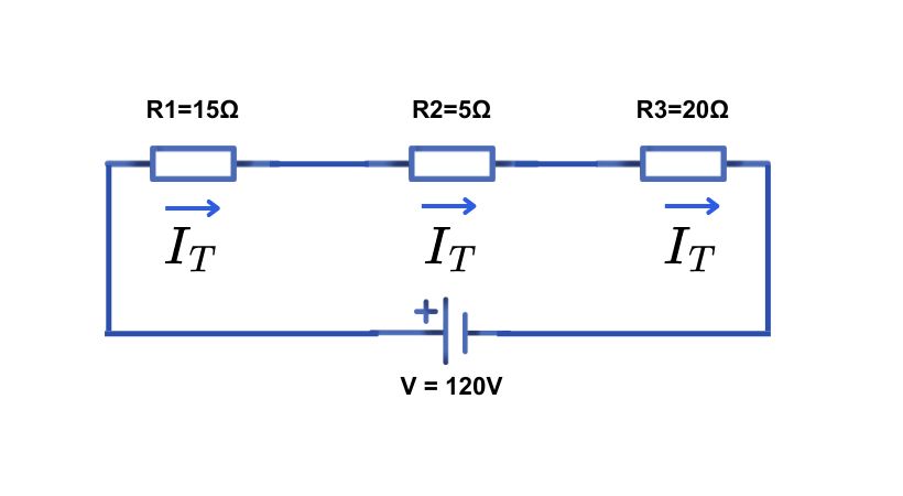
In the given circuit we have three resistors connected in series across a 120V battery.
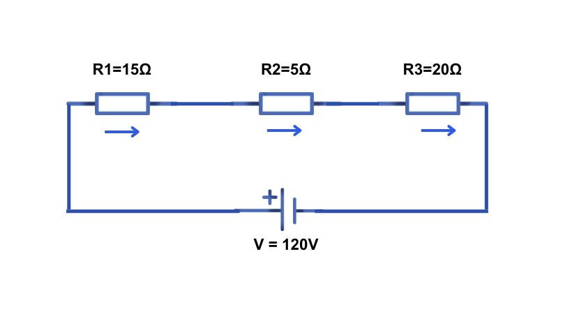
In a series circuit, the equivalent resistance is equal to the sum of the individual resistance in the circuit. As in the above circuit, we have three resistors so
R_eq = R1+R2+R3
R_eq = 15+5+20
R_eq = 40Ω
As the circuit has only one path, the same current will flow in each resistor. So
I_T = I_1 = I_2 = I_3
Using Ohm’s law we can find the total current. The total current is given by
I_T = V_T/R_eq
As we know V_T = 120 and R_eq = 40Ω
I_T = 120/40
I_T = 3A
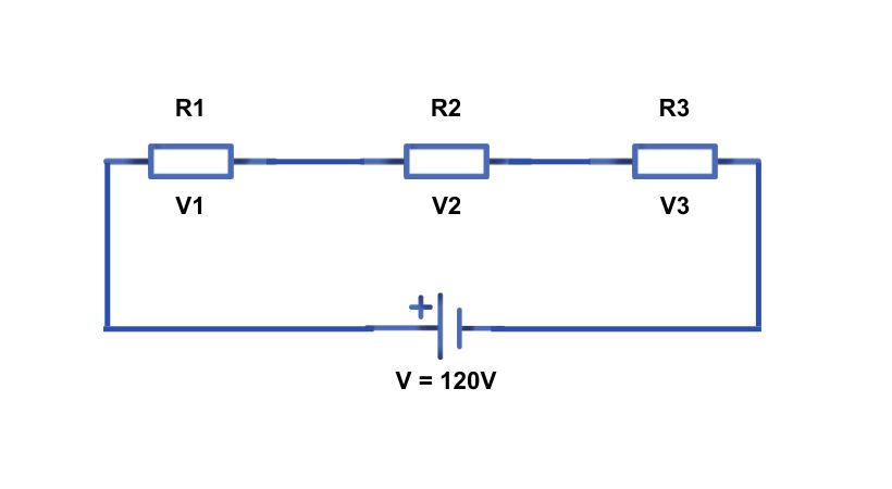
Now we can find the voltage drop for each component and the total voltage is equal to the sum of all the individual voltage drops in the circuit.
Using Ohm’s law
V_1 = I_T*R_1
V_1 = (3A)(15Ω)
V_1 = 45V
For resistor two
V_2 = I_T*R_2
V_2 =(3A)(5Ω)
V_2 = 15V
Voltage across resistor three
V_3 =I_T*R_3
V_3 =(3A)(20Ω)
V_3=60V
The total source voltage is equal
V_T = V_1 + V_2 + V_3
V_T = 45V+15V+60V
V_T = 120V
As you can see the applied voltage is distributed across each resistor.
Example no. 2
Let’s consider another example of a series connection.
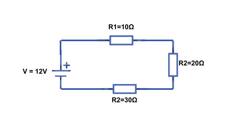
In this example, we have three resistors and they are connected in series with the voltage source.
First, we have to find the current in the circuit so the equivalent resistance is equal to…
R_eq = R1 + R2 + R3
R_eq= 10 + 20 + 30
R_eq= 60 Ω
Now the current across the circuit is
I_T = V_S/R_T
I_T = 12/60
I_T = 0.2A
As the resistor is in series so the current across it same so it will be 0.2A. The voltage will be divided, and the voltage across each resistor can be found by
V_1 = I_T*R_1
V_1 =(0.2)(10)
V_1 = 2V
In the same way, we can find the voltage across each resistor. Find the voltage drop in the other two resistors and verify if the calculated voltage is equal to the applied voltage.
Advantages
The following are a few benefits of series circuits:
- Series circuits are simple to design and require few wires to construct them.
- All components share the same current, making it easy to calculate the circuit’s total current.
- They consume less power when compared to parallel circuits, as the current remains the same across components.
Disadvantages
Series circuits also have some drawbacks.
- If one component in a series circuit fails, the entire circuit stops working.
- The voltage is divided among components, meaning each component gets less voltage as more are added, which may reduce performance.
- If one component gets short it will cause an increase in current in all components and will damage it.
- Series circuits are not suitable for complex or high-power applications due to their limited voltage and current distribution.
Conclusion
Understanding series circuits provides a foundation for comprehending more complex electronic systems. It offers a base for understanding complex electronic circuits.
In the series circuit, the components are connected in line and provide only one path for the current to flow. The same current passes sequentially through each component, as opposed to branching out.
The voltage is not the same across each component and the voltage drop depends upon the resistance of the component.
The total voltage is equal to the sum of all individual voltage drops in the circuit and the equivalent resistance of the circuit is equal to the sum of individual resistance in the circuit.
The main disadvantage of the series circuit is if one component stops working it will affect the entire circuit functionality.
So this was all about the series circuits, I hope it will be helpful.
Thank you…
Other useful posts: