Short circuits using multimeter (Verification, 2025)
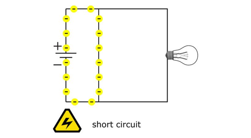
A short circuit occurs when there is an unintended connection between two points in an electrical circuit with different voltage potentials.
The short circuit creates a low resistance path which allows the excess current to flow through it overload the circuit and potentially cause damage. The multimeter resistance and continuity modes help in identifying the short circuit. The resistance mode displays zero or very low resistance values which indicate the presence of a short circuit between two points and the continuity mode produces a beep sound when detecting a short circuit.
This article will provide you with a comprehensive guide on verifying short circuits using multimeter.
Short circuit
A short circuit occurs when an intended connection is formed between two points with different potential differences. This creates a low resistance path for current to flow.

The short circuit results in an excessive current flow, which can potentially lead to damage to the circuit, overheating, and even fires.
Short circuits can happen due to various reasons, including damaged insulation, exposed wires touching each other, or faulty components.
When a short circuit occurs, the electrical resistance between the two points drops significantly, allowing a large amount of current to flow through the circuit. This increased current can overload the circuit components, leading to damage.
To avoid the short circuit, the detection of the short circuit becomes essential. A tool like a multimeter which is a very useful tool for engineers and beginners can be used to verify the presence of the short circuit.
Let’s discuss the use of the multimeter for short-circuit verification.
Short-circuit verification
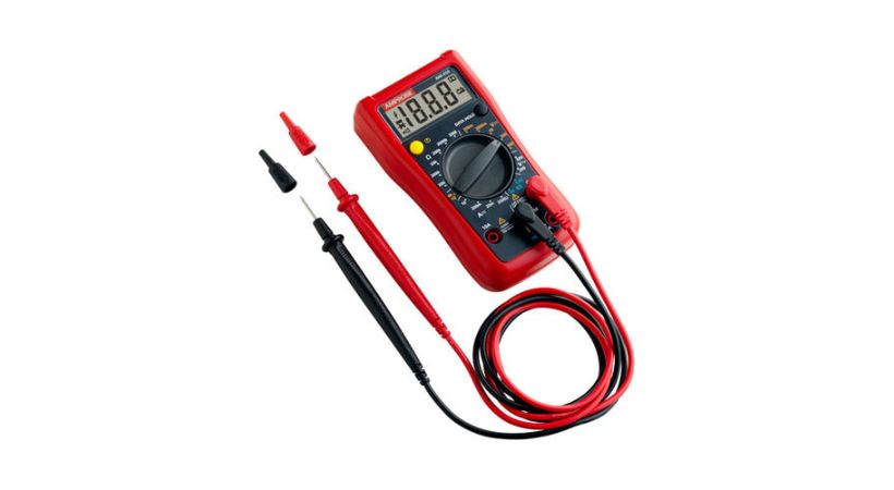
Multimeters are versatile instruments capable of measuring voltage, current, and resistance. Along with these measurements, the multimeter also offers continuity mode to check the faulty components and continuity.

For the verification of open and short circuits, the multimeter can play a significant role.
When verifying short circuits, multimeters are primarily used in continuity or resistance mode.
We’ll discuss both modes of the multimeter to make your verification process easy.
Let’s see the step-by-step guide for both continuity and resistance mode.
1. Continuity mode
The continuity mode of the multimeter checks the continuity of the flow of the current.
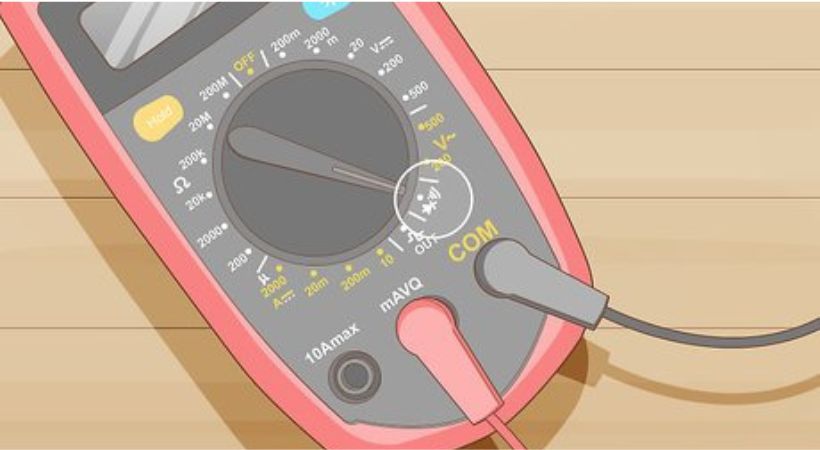
Select continuity mode: Take out your multimeter, check for damage, and set it to continuity mode. This mode is usually denoted by a symbol resembling two overlapping triangles or a sound wave icon. Refer to your multimeter’s user manual if you’re unsure how to switch to continuity mode.

Insert the probes: Connect the testing probes to the multimeter. But before connecting check the probes for any visible damage that can affect the measurement process. Two testing probes are used, connect the black probe to the COM jack and the red probes to the VΩ jack of the multimeter.
Power off: The next step is to ensure that the power source to the circuit you’re testing is turned off and disconnected. This step is crucial for safety to prevent electrical shocks and damage to the multimeter.
Probe placement: Identify the points in the circuit you may think can have a short circuit. These points could be between wires, components, or connections. It’s helpful to have a clear understanding of the circuit’s schematic diagram or layout.
Touch the probes to the circuit: After identifying the points in the circuit, now its time to connect the multimeter probes to verify the short circuit presence. Touch one probe at one end and the other probe at the other end. Ensure that the probes make good contact with the circuit points. You may need to expose a small section of wire insulation to ensure direct contact.
Observe multimeter response: When the probes contact the circuit points, the multimeter should emit a continuous beep or sound to indicate the short circuit. If the multimeter does not emit a sound or beep, there is no continuity between the tested points and the circuit is open.
Interpret results: If the multimeter emits a continuous beep, it suggests the presence of continuity, indicating a potential short circuit between the tested points. If there is no beep, it indicates no continuity, meaning there is no short circuit at those points.
By following these steps you can effectively identify the short circuit and correct it which helps in troubleshooting the electrical systems.
2. Resistance mode
If your multimeter doesn’t have continuity mode, the resistance mode can also be used to verify the short circuit.
Let’s discuss how resistance mode can be used for short circuit verification. Follow the following steps.
- Turn on the multimeter and set it to the resistance (ohms) mode. This mode is typically denoted by the Ω symbol.
- Insert the testing probes, black in COM and red in VΩ.
- Turn off the power to the circuit to ensure safety.
- Find the points in the circuit, you suspect can have a short circuit.
- Touch the multimeter probes to the two points in the circuit where you suspect a short circuit may be occurring.
- Connect one probe at one end and the other probe to the other end.
- If the resistance reading on the multimeter is close to zero ohms or significantly lower than expected for that part of the circuit, it indicates the presence of a short circuit.
- If the resistance reading is infinite (overload) or very high, it suggests there is no short circuit between the tested points.
By following these step-by-step procedures, you can effectively use a multimeter in resistance mode to verify short circuits in electrical circuits, identify the root cause of the issue, and implement necessary repairs.
Safety precautions
Safety precautions are a must whenever you are working with electrical and electronic circuits.
Here are some essential safety precautions when verifying short circuits.
- Ensure that the power to the circuit is off or disconnected before performing the test.
- Always wear personal protective equipment such as insulated gloves, and safety goggles to protect yourself.
- To verify a short circuit, select the appropriate mode of the multimeter.
- Keep the work area tidy and free of clutter to reduce the risk of accidents.
- Double-check all the connections before taking measurements and handle the multimeter carefully.
You can minimize risks and hazards associated with verifying short circuits using a multimeter by following the above safety precautions.
Conclusion
Using a multimeter to verify short circuits is a basic step in electrical maintenance and troubleshooting.
The short circuit is an unintended connection in the circuit that gives a low resistance path for the current to flow.
Short circuits commonly result from damaged insulation, exposed wires touching each other, or faulty components.
Finding short circuits is essential for the proper functionality of the system. The multimeter, a versatile tool in electrical and electronic engineering, is used to verify the presence of the short circuit.
The resistance and continuity mode of the multimeter identify short circuits. The multimeter beeps in continuity mode when it finds a short circuit.
In the resistance mode, if the multimeter shows zero or very low resistance than the expected value, then there is definitely an unintended connection or short circuit.
This was all about the verification of short circuits using multimeter. I hope it will be helpful.
Thank you…
Other useful posts:
